Getting Started
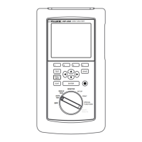
Main Unit Features
2
2-13
Table 2-4. Main Unit Features
Item Feature Description
1 Rotary Switch Selects the test tool’s modes.
2
e
Exits the current screen.
3
F
Model DSP-2000 only. Automatically provides more specific information on
the cause of an Autotest failure.
4
T
Starts the highlighted test or restarts the test last run.
5
! @
#$
Provide functions related to the concurrent display. Softkey functions are
shown in the display area above the keys.
6
Display A LCD display with backlight and adjustable contrast.
7
L R U D
Allow left, right, up, and down movement on the display. Increase or
decrease the numerical values of user-definable parameters.
8
S
Saves Autotest results and parameter changes in memory.
9
E
Selects the highlighted item from a menu.
0
C
WAKE UP
Controls the display backlight. Pressing for 1 second allows adjustment of
the display contrast. Reactivates the test tool when the tool is in power
down mode.
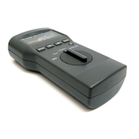
f
RS-232C serial
port
A 9-pin
connector for interfacing with a printer or host computer via a
standard IBM-AT EIA RS-232C serial cable.
g
AC adapter/
charger jack
Connection for the ac adapter/charger
supplied with the test tool.
h
AC power
indicator
LED Style 1: A green LED that turns on when the test tool is powered with
the ac adapter/charger.
LED Style 2: A multicolor LED with four states:
Off: AC adapter/charger is not connected, or is connected without the
battery pack installed.
Blinking Red: The ac adapter/charger is trickle charging the battery in
preparation for fast charging. This mode indicates an extremely low
battery voltage. The test tool may not operate.
Steady Red: The ac adapter/charger is fast charging the battery.
Steady Green: Fast charging is complete. The ac adapter/charger
continues to trickle charge the battery.
i
RJ45
connector(s)
A shielded 8-pin jack for shielded and unshielded twisted pair cable. On
Model DSP-2000, this jack is labeled CABLE TEST. Model DSP-2000 has
an additional RJ45 jack labeled MONITOR, which is used for
10/100BaseTX traffic and hub tests.
j
BNC connector Model DSP-100 only. A connector for coaxial cable.