1586A
Calibration Manual
12
Thermistor Verification Steps
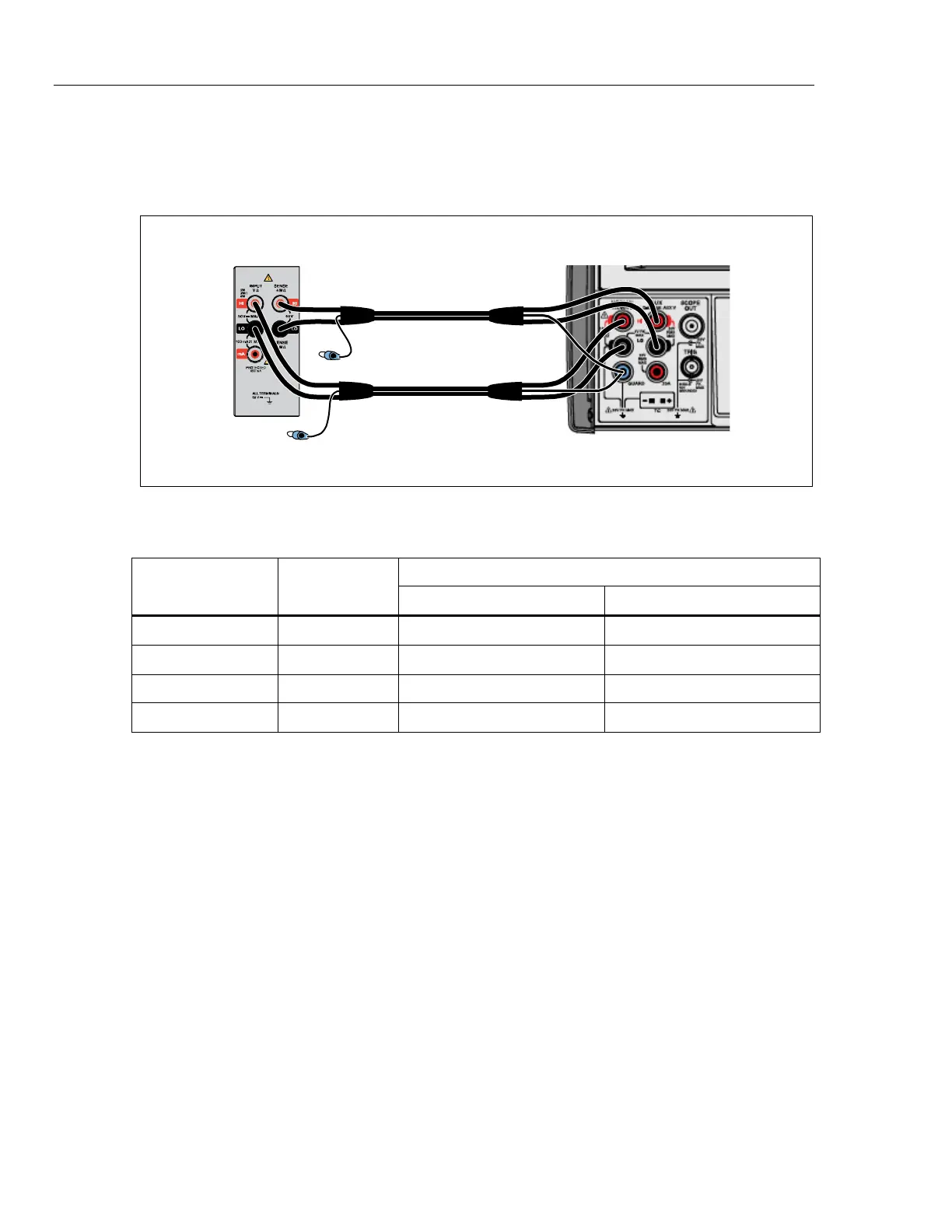
Connect the Product to the test equipment as shown in Figure 5 and apply the
resistance listed in Table 6. Configure Ch001 as a 4-wire thermistor function with
resistance display.
5522A CalibratorUUT
NC
NC
hcn204.wmf
Figure 5. Thermistor Test Equipment Setup
Table 6. Thermistor Verification Steps
Nominal
Input
Range
1-Year Test Limits
High Low
0 Ω 2.2 k 0.2 Ω -0.2 Ω
2 kΩ 2.2 k 2000.28 Ω 1999.72 Ω
90 kΩ 98 k 90004.1 Ω 89995.9 Ω
900 kΩ 1 M 900140 Ω 899860 Ω