0.25" / 1 cm
4
8
5
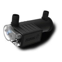
7
9
11
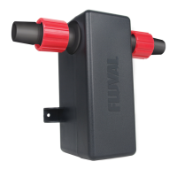
4. Slidemetalclampoverendoflter
output hosing (approx. 0.25" / 1 cm
from end) and attach to UVC connector
(eithersideastheUVCworksin
both directions).
5. SlideUVCunitintomountingbracket
untilitclicksintoplace.
6. Slide metal clamp over one end of
1" / 25 mm FX hose for cabinet mount
(sold separately – # A20233) or
equivalent1"/25mminnerdiameter
vinyl hose (sold separately). Ensure
clamp is positioned approx. 0.25"
/ 1 cm from end.
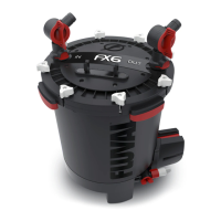
7. Slide metal clamp over other end of
1" / 25 mm connection hose (approx.
0.25" / 1 cm from end) and attach
tolterOUTvalve.IMPORTANT:
For optimal performance, ensure all
hosing follows a straight path with
no loops and very little slack.
8. Doublecheckallmetalclampsare
positioned approx. 0.25"/ 1 cm from
ends and are tightly secured with a
screwdriver to ensure watertight seal.
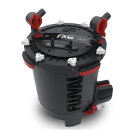
9. OpenlterINandOUTvalvesandwait
15 minutes to ensure connections
are watertight.
10.PluginFXlterintoelectricaloutlet.
The electronic automatic priming
sequencewillbegin.
11.Ensurewaterisowingoutfrom
lter.Oncecompleted,connectpower
supply to UVC unit and plug into
electrical outlet. A light indicator
(visible through the semi-transparent
lamp cover) will show that the UVC
unit is operating.
6
4
 Loading...