BB
AA
3. Slide metal clamps over each of
the two 1" / 25 mm to 5/8" / 16 mm
hosing adapters (approx. 0.25" / 1 cm
from end).
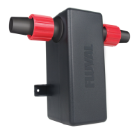
4. Installhosingadaptersoneach
UVC connector.
INSTALLATION ON CABINET WALL WITH
CANISTERFILTERSUSING5/8" / 16 mm HOSING
IMPORTANT:
•Thisinstallationoptionrequiresone5/8"/16mminnerdiametervinylhose
(soldseparately).
•Self-tappingscrewssuppliedwithUVCunitaresuitableforwoodencabinet
wallswithaminimumthicknessof0.6"/15mm.Installationisnot
recommendedonmovingelements(i.e.cabinetdoors).
•UVCmustbeconnectedtolteroutputhosingonly.NeverinstallUVCto
lterintakehosing.
•EnsureUVCandhosingarealwayspositionedaboveltercover.
PREPARING YOUR FILTER
1. Iflterisequippedwithvalves,ensuretheyaresettotheclosedposition.
2. Unpluglterfromelectricalpowersupply.
3. PriortoUVCinstallation,refertoyourltermanualforhosedisassembly
procedure.Outputhosemustbeemptiedofanywaterbeforestartingthe
UVC connection process.
4. Disconnectoutputhosefromlter,ensuringotherendofhoseremainsinaquarium.
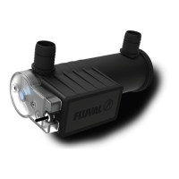
ADDING THE UVC UNIT
1. Select desired UVC location on cabinet wall.
2. Usingascrewdriver,axmountingbracket
to cabinet wall using screw holes (A) for
horizontalpositioning,orholes(B)for
vertical positioning.
IMPORTANT: If installing horizontally, ensure mounting bracket is placed so
that the screw holes appear below the Fluval logo.
2 HORIZONTAL 2 VERTICAL
3
4
5
6
5. Slidemetalclampoverendoflter
output hosing (approx. 0.25" / 1 cm
from end) and insert into hose
adapter (either side as the UVC
worksinbothdirections).
6. SlideUVCunitintomountingbracket
untilitclicksintoplace.
5
 Loading...