Do you have a question about the Fly Sky FS-GT2 and is the answer not in the manual?
Explanation of symbols like Danger, Warning, and Attention for operational safety.
Marks indicating forbidden actions and required procedures for safe operation.
Guidance on avoiding adverse weather, pre-flight checks, and proper power-up/shutdown sequences.
Check battery charge before use; low charge can cause loss of control. Charge immediately when low.
Use dedicated chargers. Disconnect power after charging. Remove batteries when not in use to prevent damage.
Steps for installing battery, connecting charger to power and transmitter, and disconnecting power.
Steps for connecting charger to power and receiver, and disconnecting power after charging.
Details on channels, model type, RF power, modulation, sensitivity, voltage warning, ports, power, weight, size, color, and certifications.
Details on channels, model type, frequency band, modulation, sensitivity, power, weight, size, color, and certifications.
Diagram and instructions for connecting receiver, switch, ESC, servos, and battery for motor-driven models.
Diagram showing connections for gas-powered models: switch, battery, receiver, throttle, and steering system.
Step-by-step guide for pairing the transmitter and receiver, including visual indicators.
Steps for connecting components and powering on the transmitter and receiver system.
Steps for safely powering down the receiver and transmitter.
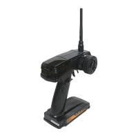
Identifies components on the front of the transmitter, including control box, antenna, steering wheel, and trigger.
Identifies controls on the side of the transmitter, such as ST REV, POWER SW, BIND, TH REV, and TRIM.
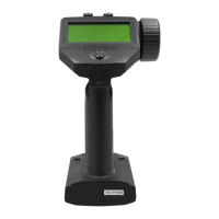
Identifies connection ports on the back of the transmitter, such as CHARGER and DSC.
Explains how the steering function controls the direction of the model and how to adjust sensitivity with the D/R knob.
Explains how the throttle trigger controls speed, acceleration, braking, and reverse functions.
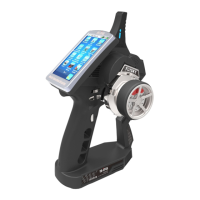
Instructions for connecting the transmitter to a PC for virtual RC racing practice using VRC software.
| Channels | 2 |
|---|---|
| Modulation | GFSK |
| Receiver | FS-GR3E |
| Frequency | 2.4GHz |
| Power | 6V |
| Battery | AA |
| RF Power | <20dBm |