8
8. Propeller
The propeller is three-bladed and the blades have a
large width and a thin profile, a smooth surface and
are back-swept. This gives a highly efficient and clog-
free operation.
The propeller angle can be adjusted to meet
requirements. Angles between 4° and 19° are
possible, but restricted upwards depending on version
and applications due to available power.
9. Flush protection
The mixer and the PP-pump can be equipped with
accessories for water or air flushing systems. Flushing
the propeller hub area and the outer seal reduces the
risk of sticking when mixing reactive slurries.
10. Cutting rings
The propeller can be equipped with cutting rings to
prevent clogging of the hub area.
The cutting rings can be used with or without flushing.
These are intended to be used for mixer applications,
where liquids with long fibres are to be mixed.
11. Seal protector
The mixer and PP-pump can be equipped with seal
protector to prevent clogging.
12. Fixing plate
The mixer is available with two types of fixing plate,
one for guiding bar installation and one for flange
mounted mixer.
13. Cooling jacket
Normally the stator is cooled by the surrounding liquid.
External cooling (cooling jacket) is available as option.
14. Vortex protection shield
In order to avoid vortex the machine can be equipped
with a protective shield.
15. Jet ring for mixer
The mixer can be operated with or without a jet ring.
The jet ring improves the efficiency and directs the jet.
NOTE. Operation without jet ring affects the
power consumption.
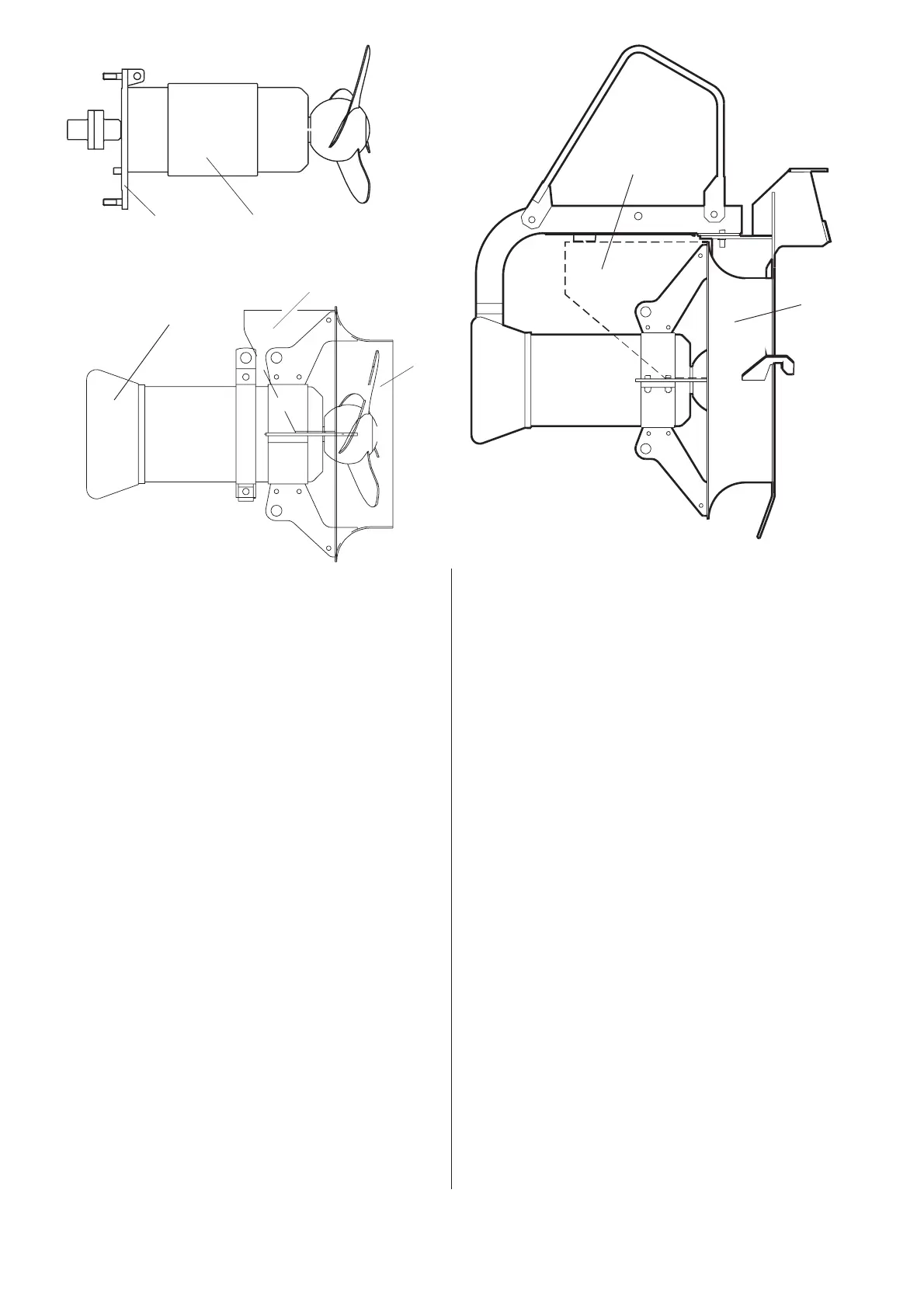
16. Inlet cone for PP-pump
The inlet cone is designed to give the best influence
on the created flow .
Discharge connection for PP-pump
The function of the discharge connection is to fix the
inlet cone onto a pipe or a diffusor.
Guiding equipment for PP-pump
The guiding equipment consists of two pipes (guide
bars) and upper guide bar holders.
Installation for PP-pump
The PP-pump should be installed horizontally on a
wall and guided vertically along the wall.
The pump slides down along guide bars and connects
automatically to the discharge connection. The flange
of the inlet cone directs the pump at guiding and
secures the correct position on the discharge con-
nection.
14
16
15
14
12
12
11
40340
12
13