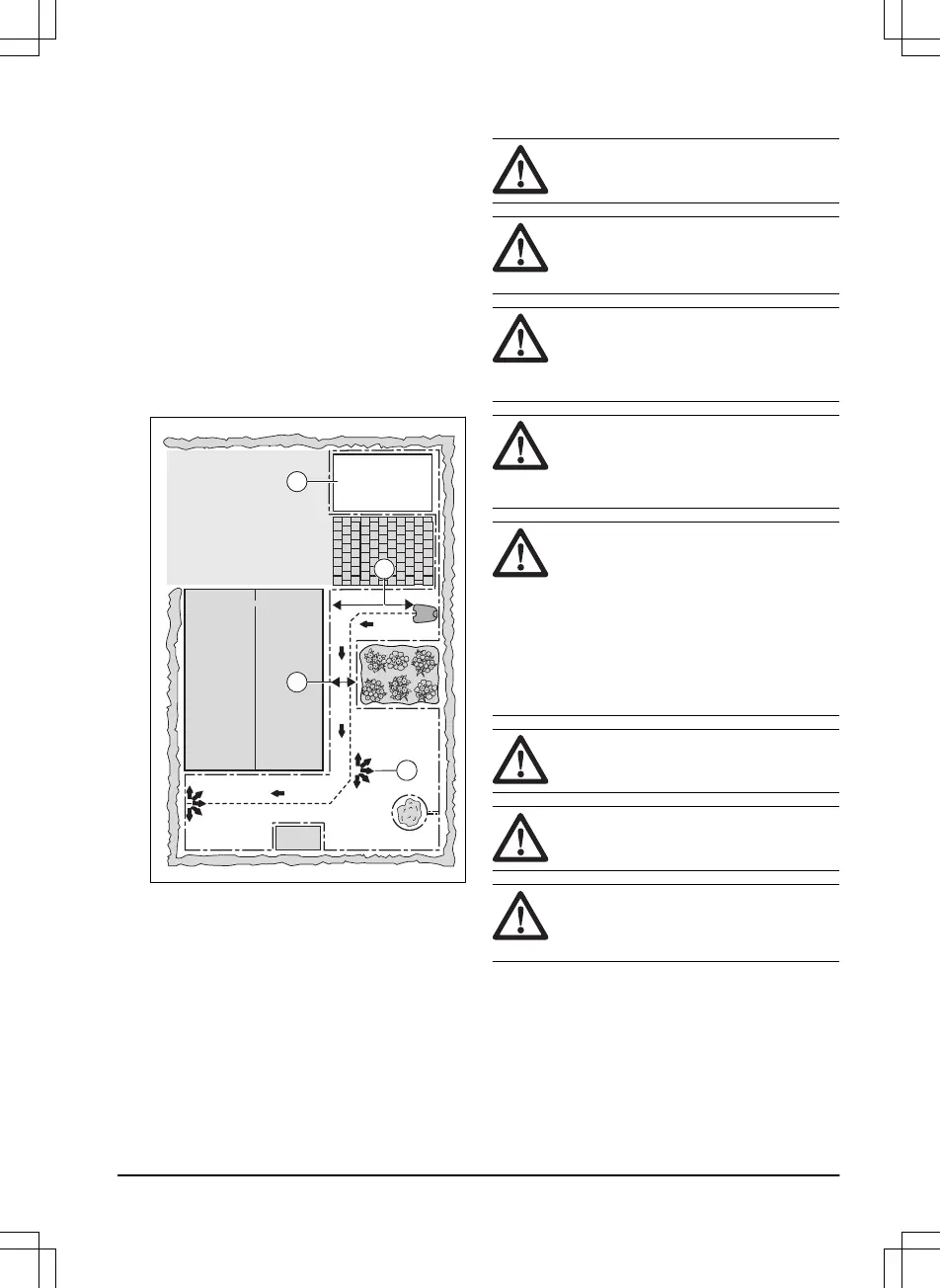
• If the work area has a passage (B) with no guide
wire installed, the minimum distance between the
boundary wires is 2 m / 6.5 ft. With a guide wire
installed through the passage, the minimum
distance between the boundary wires is 60 cm / 24
in. Use the
PassageSense
function to cut this
passage, Refer to
Lawn Coverage and
PassageSense on page 21
.
• If the work area has areas which are connected by
a narrow passage (B), you can set the product to
first follow and then leave the guide wire after a
certain distance (C). The settings can be changed
in
Lawn Coverage and PassageSense on page
21
.
• If the work area includes a secondary area (D),
refer to
Secondary area on page 24
. Put the
product in the secondary area and select
Secondary area mode
.
3.5 Installation of the product
3.5.1 Installation tools
• Hammer/plastic mallet: To simplify putting the
stakes into the ground.
• Edge cutter/straight spade: To bury the boundary
wire.
• Combination pliers: For cutting the boundary wire
and pressing the connectors together.
• Adjustable plier: For pressing the couplers
together.
3.5.2 To install the charging station
WARNING: Obey national regulations
about electrical safety.
WARNING: The product is only to be
used with the power supply unit supplied by
Flymo.
WARNING: Do not put the power
supply at a height where there is a risk it can
be put in water. Do not put the power supply
on the ground.
WARNING: Do not encapsulate the
power supply. Condensed water can harm
the power supply and increase the risk of
electrical shock.
WARNING: Risk of Electric Shock.
Install only to a residual-current device
(RCD) with a tripping current of maximum 30
mA when connecting the power supply to
the power outlet. Applicable to USA/Canada.
If power supply is installed outdoors: Risk of
Electric Shock. Install only to a covered
Class A GFCI receptacle (RCD) that has an
enclosure that is weatherproof with the
attachment plug cap inserted or removed.
CAUTION: Do not make new holes in
the charging station plate.
CAUTION: Do not put your feet on the
baseplate of the charging station.
WARNING: The power supply cable
and extension cable must be outside the
work area to avoid damage to the cables.
When connecting the power supply, only use a power
outlet that is connected to a residual-current device
(RCD).
1. Read and understand the instructions about where
to put the charging station. Refer to
To examine
where to put the charging station on page 12
.
2. Put the charging station in the selected area.
1622 - 001 - 03.03.2021
Installation - 17