3
Assembly Instructions
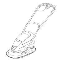
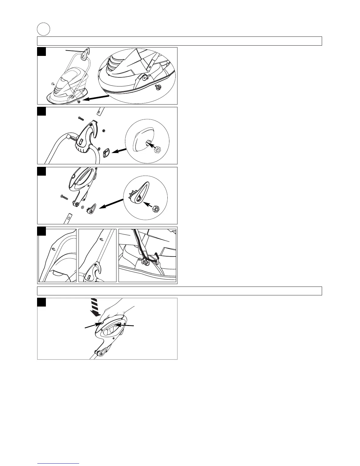
Assembly of lower handle to hood (A)
1. Place the ends of the lower handle into the slots
ensuring that the joint is facing the correct way
(A1).
2. Secure lower handle to hood by firmly pushing fix-
ing pin through holes in hood and handle (A2).
3. Repeat on the other side.
• NOTE
Should a problem occur when securing handle
with the fixing pin, carefully lever the pin out of
location and repeat steps 1 to 3 above.
Assembly of handle tube to joint (B)
1. Ensure that the joint is centralised on the lower
handle.
2. Line up the hole in the joint with the hole in the
lower handle.
3. Insert the square headed bolt through the hole in
the joint and the hole in the lower handle.
4. Insert an M6 nut into the lower wing knob.
5. Fit washer, then wing knob and tighten.
6. Insert handle tube into joint, lining up the holes.
7. Insert screw through joint and handle tube. Fit M5
nut and tighten screw.
Assembly of switch handle to handle tube (C)
1. Insert the handle tube into the switch handle,
ensuring the handle is in an upright position and
lining up the holes.
2. Push bolt through the holes.
3. Insert M6 nut into the upper wing knob.
4. Fit washer, then wing knob and tighten.
Cable clips (D)
1. Fit the cable to the handles with the clips provided.
2. Ensure the the cable is secured under the clip on
the hood.
A
B
C
D
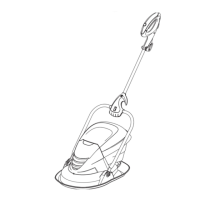
Starting and Stopping
E
Starting
1. Hold as illustrated in Figure E.
2. To start, press the lock-off button down, whilst
pressing the lock-off button, squeeze the switch
lever.
Stopping
1. To stop your product, release the switch lever.
Lock-off button
Switch lever
1
2