Do you have a question about the FlySky FS-i6 and is the answer not in the manual?
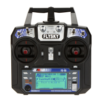
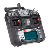
Details on the Flysky FS-i6 transmitter, including channels, RF, power, and physical attributes.
Details on the Flysky FS IA6 receiver, including channels, frequency, power input, size, and features.
Explanation of how transmitter sticks control the sails (left stick) and rudder (right stick) for RC sailboats.
Description of left and right stick movements for sail trim and rudder control, including spring-loading.
Mapping of transmitter stick movements (Throttle/Aileron) to RC sailboat functions (Sails/Rudder).
A diagram illustrating how servos connect to the FS IA6 receiver for various functions.
Instructions on how to reverse the direction of servo movement via the transmitter settings.
Steps for electronically pairing the transmitter and receiver to prevent interference.
This document describes a radio control system, specifically the Flysky FS-i6 Transmitter paired with an FS IA6 Receiver, primarily for use with RC sailboats, though it is also suitable for gliders and helicopters. The system allows for remote control of model functions, translating user input into physical movements of the model.
The core function of this system is to provide wireless control over a model. The transmitter, a handheld radio, sends control input signals to a small receiver mounted inside the model. This receiver then communicates with servos, which are small motor and gearbox units. These servos convert the electrical signals from the receiver into mechanical motion, typically rotational, which is then translated into linear motion by a servo arm. For RC sailboats, this system controls two primary functions: the rudder and the sails (jib and main). The sail winch arm adjusts both the jib and main sails simultaneously using a single servo.
The system operates on a 2.4GHz frequency, utilizing AFHDS 2A and AFHDS 2.4G systems for reliable communication. This binding process electronically links the transmitter and receiver, preventing interference from other radio systems. While the units may arrive pre-bound, a simple binding procedure is outlined for new setups or re-binding.
The transmitter features two control sticks: a left stick and a right stick, both mounted on gimbals allowing for up/down and left/right motions. For RC sailboats, common practice dictates using the left stick for sail control and the right stick for rudder control.
The left stick's up/down motion is not spring-loaded, meaning it will stay in the position it is moved to, allowing the sails to remain in a desired configuration. Moving the left stick fully "Up" lets the sails out completely, ideal for running downwind. Moving it fully "Down" pulls the sails in tight, suitable for beating close-hauled. The left stick's left/right motion is not utilized in RC sailing.
The right stick's left/right motion, used for rudder control, is spring-loaded. This means it will automatically return to the center position when released, causing the rudder to return to its neutral position. Moving the stick right turns the boat to the right (starboard). The right stick's up/down motion is not used for sailboat control.
The operator manual designates channels based on RC aircraft usage. For sailboats, the left stick's up/down motion corresponds to the "Throttle" on Channel 3, controlling the sails. The right stick's left/right motion corresponds to the "Aileron" on Channel 1, controlling the rudder.
To enhance user comfort and control, the radio includes an attachment point on its face for a lanyard. This allows the user to wear the radio around their neck, preventing fatigue and providing stability, especially when leaning over to launch the boat, and crucially, keeping the radio out of the water.
A key feature for customization is the servo reverse function. If, after installation, a servo moves in the opposite direction to the control input (e.g., pushing the right stick right turns the rudder left), this function allows the user to easily reverse the servo's direction. This is particularly useful when servos need to be mounted in unconventional orientations due to space constraints within the model. The process involves navigating the transmitter's menu to select the desired channel and toggling between "Normal" and "Reverse" settings.
The system is powered by 1.5AA batteries (four required) for the transmitter, and the receiver operates on a 4.0-8.4V DC input. The transmitter includes a display mode with a transflective STN positive type screen, featuring a 128x64 dot matrix with white backlight, providing clear visibility of settings and status.
While the system is robust, it's important to note that the receiver and servos are explicitly stated as NOT WATERPROOF. This necessitates careful installation within the model, ideally high inside the hull and away from areas where water might ingress. Even with a well-built boat, gusty conditions can lead to water getting onto the deck, especially when going downwind. Therefore, it is recommended to keep a small sponge handy to remove any water that finds its way into the boat's interior.
A good practice for long-term maintenance and to prevent moisture-related issues is to store the boat with the hatch cover off. This allows any accumulated moisture inside the hull to evaporate, protecting the electronics.
The system supports online updates, indicating that firmware improvements or bug fixes can be applied, ensuring the system remains current and performs optimally over time.
The binding procedure, while primarily for initial setup, can also be considered a maintenance feature. If the transmitter and receiver ever lose their electronic link, or if a new component is introduced, the binding process allows the user to re-establish communication, ensuring continued functionality. The process involves connecting a supplied bind cable to the receiver, applying power, holding a "BIND KEY" on the transmitter during power-on, and then reconfiguring power to the receiver. It's crucial to ensure the transmitter is off before connecting the battery lead to provide power during this process.
Overall, the system is designed for ease of use and reliability in remote control applications, with clear instructions for setup, operation, and basic troubleshooting.
| Channels | 6 |
|---|---|
| Modulation Type | GFSK |
| RF Power | <20dBm |
| Weight | 392g |
| Antenna Length | 26mm |
| Display | LCD |
| 2.4GHz System | AFHDS 2A |
| Stick Resolution | 1024 |
| Low Voltage Warning | Yes |
| DSC Port | PS2; Output: PPM |
| Chargeable | No |
| Display Type | LCD |
| Model Memory | 20 |
| Dimensions | 174x89x190mm |
| Power Supply | 6V DC (1.5AA x 4) |
| Model Type | Helicopter |
| Voltage Range | 6.5V |
| Frequency Range | 2.405 - 2.475GHz |