18
STEP 53: Place the aircraft upside down. Using a ruler, measure back
exactly 7 inches from the point where the leading edge of the wing
intersects the fuselage and make a small dot on the underside of the
wing. This measurement is critical as it will determine the CG of the
airplane, so take your time. Using a square, extend a line from this
point you just made perpendicular to the fuselage. If you don’t want
to mark on the airplane, use tape so you can remove it later.
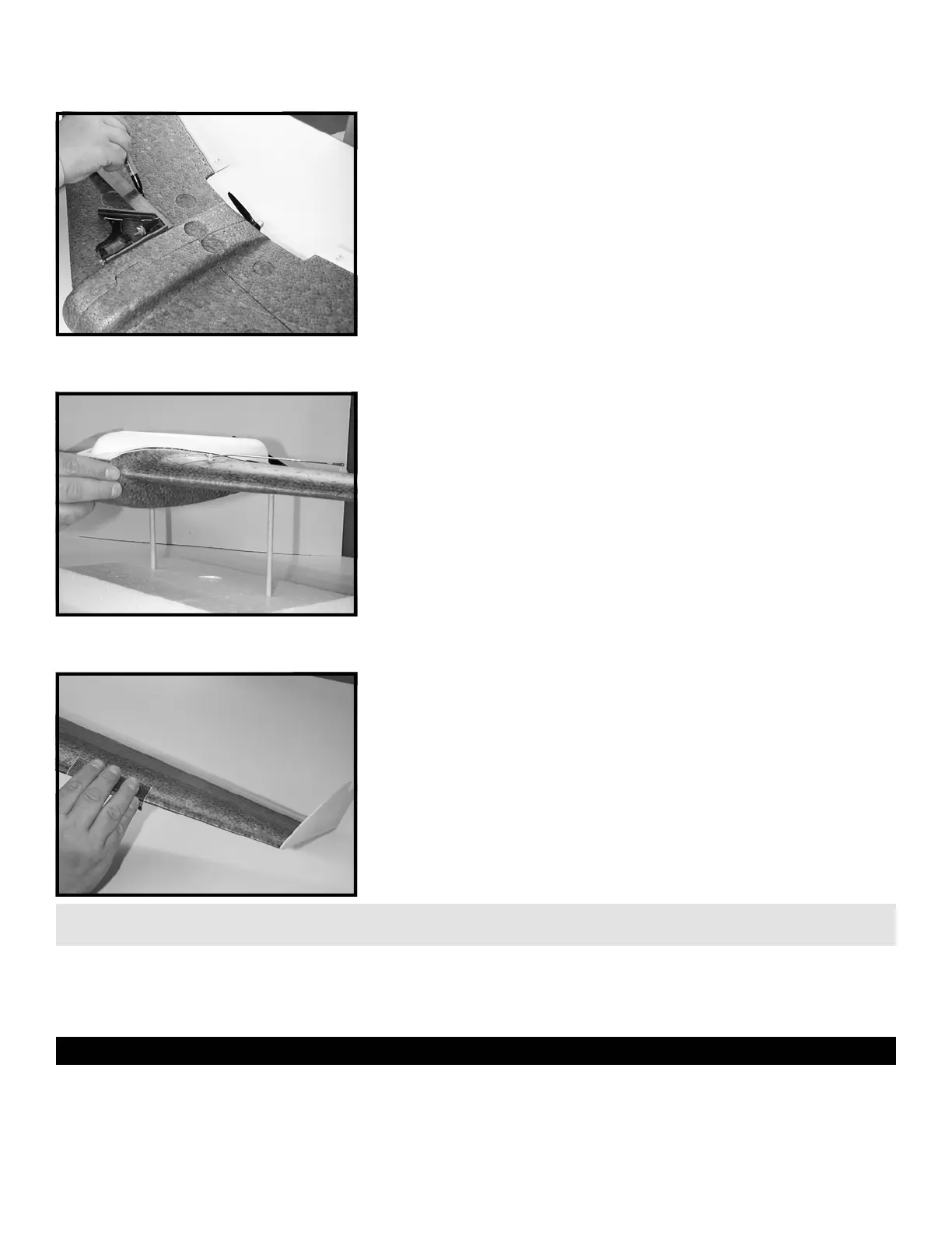
STEP 54: With all equipment installed (including the battery), and the
canopy shut, check to make sure the plane balances within ±1/4” of
the CG line marked in STEP 53. The illustration shows the plane
balanced on two dowel rods inserted into a piece of foam for this
purpose. If the airplane was constructed in accordance with this
manual, it should balance on the CG with the batteries pushed all the
way to the front of the battery compartment. If your airplane is nose
heavy, slide the battery back until it balances. If the plane is tail
heavy, consider cutting down the winglets or sanding the elevons
before adding ballast to the nose. With the CG set properly and with
2 degrees of up elevon, the plane should glide level.
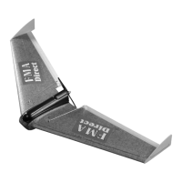
STEP 55: This step is optional on all 400 Class models but mandatory
on all 600 Class models. The 600 Class aircraft are heavier and the
wing loading is higher. To greatly improve flight handling at slow
speeds and help to prevent tip stall and snap roll, the outer 1/2 to 2/3
of the leading edge of the wing and the front of the winglet must be
sanded round. Rounding the outside of the leading edge ensures that
if the airplane begins to stall at slow speed, the wing will stall at the
center rather than at the tips, helping to prevent snap roll and making
the plane recover faster and with less difficulty. For best results, sand
about 1/4” radius into the sharp leading edge and fair it in toward the
center of the wing.
TIP: Rounding the leading edge of the wing is a trade-off between top speed and maneuverability. While a sharper leading edge will improve top
speed, a rounder one will improve handling. STEP 55 is about the best compromise to give good handling without a noticeable speed reduction.
This completes the assembly portion of the manual. If you elect to apply the FMA Direct decals or other
adornments to RAZOR, it is a good idea to clean the foam surface with alcohol before you proceed. The next
section includes basic setup information and tips for flying RAZOR based on extensive flight testing conducted by
FMA Direct engineers.
SETTING UP AND FLYING THE MODEL
OVERVIEW
If you are new to radio control, it is important that you seek the help of an experienced modeler to help you set up and learn to fly
your new RAZOR. The hardest part of learning to fly is adjusting the control surfaces and “trimming” out the model during the initial
flights. Also, no matter what your skill level, it is always a good idea to have another modeler around the first time you fly the
airplane to launch it for you. Until the airplane is trimmed to fly straight and level with little transmitter stick motion, launching can
be a bit tricky. A flying wing has many advantages over a normal design in terms of efficiency. “Tailless” wings can be built much
600 CLASS -
400 OPTIONAL
 Loading...