17
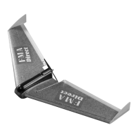
STEP 49: Screw the clevis onto the pushrods. Install the pushrods to
the servo output arms from the out-board side of the servo. Your kit
contains one left and one right pushrod. Before snapping the clevis to
the control horn, adjust the length of the rod so that when the
pushrods are installed, the elevons are set for 2 degrees up elevon.
You can judge 2 degrees as follows: the horizontal (level) axis of the
airframe is along the part line of the molded part. The part line can be
identified by small protrusions of foam that outline the entire
airframe; i.e. leading edge, trailing edge, wing tips. Hold the aircraft
such that the part line of the mold is parallel to the ground. The back
of the elevons should rise about 1/16” above this imaginary plane.
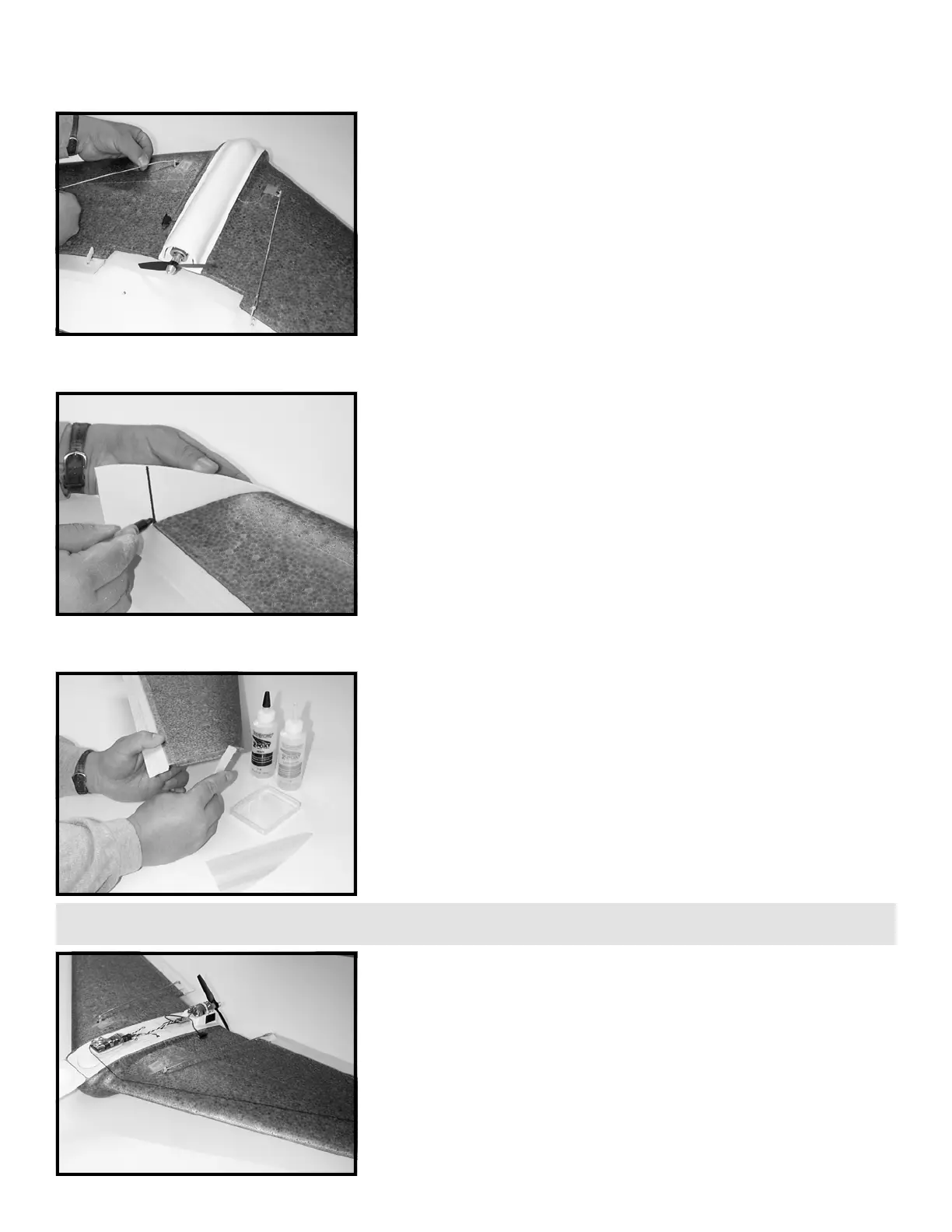
STEP 50: Round-off the top edge of the winglets. The shape of the
winglet on 400 Class kits is not critical. You may install them as is, or
you may change the size and shape to suit your tastes. For all 600
Class kits, it is mandatory that you reduce the length of the winglet
so that it does not protrude beyond the trailing edge of the wing. For
600 Class kits, hold the winglet up to the wing tip, mark and cut the
length of the winglet down as illustrated. Cutting down the winglets
for 600 Class models will greatly improve flight handling at slow
speeds, helping to prevent tip stall and snap roll.
STEP 51: Mix a modest amount of 5 minute epoxy and apply to the
wing tip. Attach winglet to wing tip and align the underside of the
winglet to match the underside of the wing airfoil. Hold or tape in
place until glue sets. Repeat for other winglet.
STEP 52: Cut a small slot 1/8” deep and 1/2” long in the top of the
wing in front of the servo and directly in line with the front of the
receiver. Press the antenna into this slot using a small blunt dowel so
as not to damage the antenna wire. Use a small piece of 0.005” (thin)
LEXAN
(TM)
tape to “capture” the antenna in the slot but allow it to
move freely back and forth through the slot. This arrangement will
keep the antenna from coming in contact with the servo mechanism
but will allow you to open the battery hatch to change/charge
batteries. Route the antenna over the top of the wing toward the
back of the winglet. Drill two small holes in the winglet just ahead of
the trailing edge of the wing. Loop the antenna through these holes.
600 CLASS -
400 OPTIONAL
TIP: Optional antenna routing...drill a small hole through the wing about 1” back from the leading edge and directly opposite the back of the receiver.
Route the antenna to the underside of the wing and angle back to the outboard trailing edge. Drill another small hole there and route antenna back up.
 Loading...