16
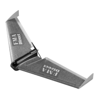
STEP 45: Using a small bit that is slightly smaller than the outside
diameter of the pushrods, open up the second hole down on the servo
arms to accept the pushrods. The fit should be tight to prevent any
slop in the linkages.
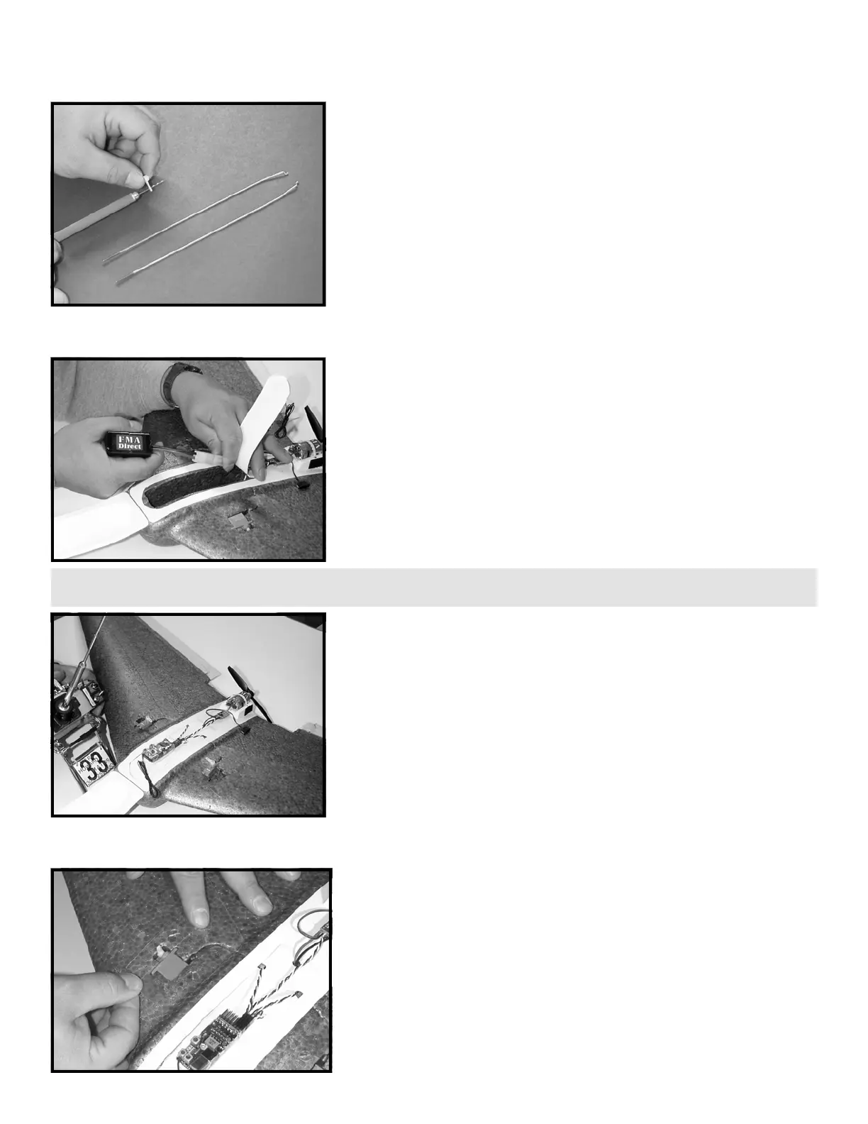
STEP 46: Make sure the ESC power switch is off. Open the canopy
and battery hatch, and install the fully charged 7 cell battery power
pack. Do not turn the power switch on at this time.
STEP 47: Position the servos up-right in the servo cut-outs. If
applicable, install the receiver crystal in the receiver and check that
the dip switches are set in accordance with the receiver manual. Be
certain the propeller is free of obstructions! Set transmitter throttle
and throttle trim controls full off, then turn on transmitter. Turn the
ESC power switch on being careful of the propeller. Check to make
sure you have the servos and ESC plugged into the correct channels
on the receiver; i.e., throttle controls throttle, elevator and aileron
control the servos. When everything is working, install and center the
servo output arms facing in as illustrated. See the section titled
“SETTING UP AND FLYING THE MODEL” for instructions on set up.
STEP 48: Put the servos back into the servo cut-outs and tape in
place using the two short pieces of tape prepared in STEP 26.
TIP: While the following steps are illustrated with the propeller installed, it is much safer to remove the propeller before applying power and leave it off
during initial setup until you’re ready to fly the airplane.
 Loading...