13
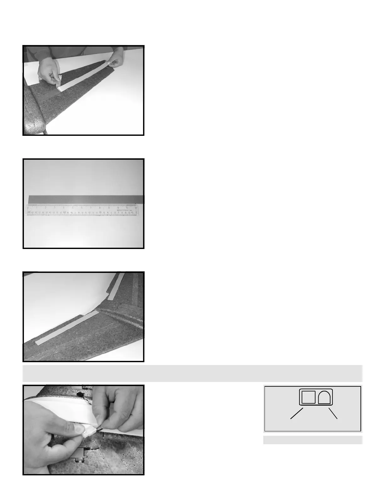
STEP 33: Turn the airframe upside down and hang the fuselage and
one wing half over the edge of the table as illustrated. Remove the
backing from the tape and place the tape on the bottom of the wing
as detailed in the previous steps. Make certain the wing is flat on the
table top so no warping of the wing can occur. Seal the tape tightly
to the wing using your thumb or a blunt object such as a screwdriver
handle. Repeat this step for the bottom of the other wing.
STEP 34: Steps 34 and 35 apply only to a 600 Class kit. If you do not
have a 600 Class kit, proceed to STEP 36. If you have a 600 Class kit,
locate the remaining piece of 0.010” LEXAN
(TM)
tape. Mark the center
of the tape and cut straight across.
STEP 35: This illustration shows the placement of the 600 Class,
additional bottom structural tapes prepared in STEP 34. Remove the
adhesive backing from the structural tape. Turn the airframe upside
down and hang the fuselage and one wing half over the edge of the
table as in STEP 33. Remove the backing from the tape and place the
tape on the bottom of the wing as illustrated. Make certain the wing
is flat on the table top so no warping of the wing can occur. Seal the
tape tightly to the wing using your thumb or a blunt object such as a
screwdriver handle. Repeat this step for the bottom of the other
wing.
STEP 36: Feed the two power wires
from the ESC through the hole in the
battery hatch. Locate the plastic,
male, Tamiya type shell. Install the
shell to the power wires by pushing
the wire leads with the connector
pins through the back of the shell as
illustrated. Be sure to maintain
proper polarity of the black and red wires as shown in the diagram.
The pins will “click” into place when they are properly seated. Test
the connection by lightly tugging on the wires after installation.
RED WIRE
BLACK WIRE
Connector Polarity
TIP: STEP 36 does not apply to the 600 “Performance” RTF as you have already made the hole large enough to accommodate the entire Deans plug.
600 CLASS ONLY
600 CLASS ONLY
 Loading...