4
MODEL: CONTAINS: CONTAINS: CONTAINS:
RZR600KIT
1 LEFT, 1 RIGHT WING
1 ELEVON PACK 2 ELEVONS
1 WINGLET PACK 2 WINGLETS
1 600 PLASTICS PACK 1 600 TRAY, 1 CANOPY
1 HARDWARE PACK 1 PUSHROD PACK 1 LEFT, 1 RIGHT PUSHROD
1 CONTROL HORN PACK 2 CONTROL HORNS, 4 SCREWS
1 MTL CLEVIS PACK 2 CLEVIS, 2 RETAINING CLIPS
ELEVON TAPE 2 PCS. 0.005” LEXAN W/ ADHESIVE
STRUCTURAL TAPE 6 PCS. 0.010” LEXAN W/ ADHESIVE
SCREEN CLOTH 1 2” X 4” 120 GRIT
MOTOR TIE 1 8” X 0.142” NYLON TIE
HOOK & LOOP TAPE 1 5/8” X 2” MALE AND FEMALE
1 22” 5.5mm CARBON SHAFT
OWNER’S MANUAL
RZR600RTF1/RZR600RTF3
RZR600KIT CONTENTS PLUS:
1 600 MOTOR PACK (ASSY) 1 600 CLASS 7.2V MOTOR “PERFORMANCE” OR “ENDURANCE”
2 0.01UF CAPACITORS
1 MINI 30 ESC
1 SHOTTKY DIODE
1 DEANS OR TAMIYA MALE “PERFORMANCE” OR “ENDURANCE”
1 PROPELLER (8 X 4)
1 600 PROP ADAPTER 1 ADAPTER SHAFT
1 SPINNER
2 HEX SET SCREWS
1 7 CELL 800AR POWER PACK
RZR600RTF2/RZR600RTF4
RZR600RTF1 OR 3 CONTENTS
PLUS:
1 MICRO RCVR FM OR AM
2 S80, S100 OR PS30 SERVOS
ASSEMBLY INSTRUCTIONS
Proceed carefully through each of the following assembly steps. Please read each step completely before you
begin that step. If you are uncertain about the instructions provided, please call FMA Direct technical assistance
at (301) 831-8980.
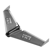
STEP 1: ARCEL
(TM)
foam contains polyethylene. While this particular
compound is the key to the strength of the foam, when parts are
injection molded using ARCEL
(TM)
, the surface finish or “skin” that
forms does not readily accept bonding agents. For this reason, it is
important to prepare the surfaces of your model for bonding by lightly
sanding the skin on the wing panels where you will apply adhesives.
When sanding ARCEL
(TM)
, use light, brisk, back-and-forth motions until
the finish is dull. Do not sand so deeply that you change the shape of
the joints - just remove the “shiny” look. Using the supplied 2” x 4”,
120 grit screen cloth, carefully sand the inside portions of both wing
halves where the wings will be joined.
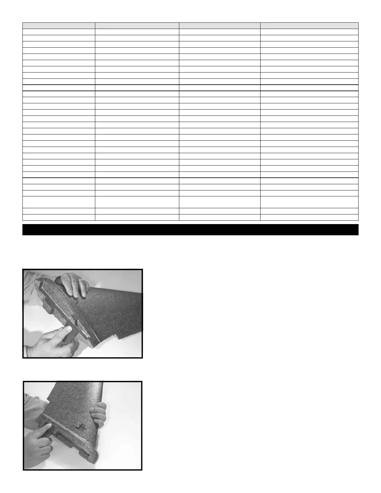
STEP 2: Using the supplied 2” x 4”, 120 grit screen cloth, carefully
sand the tops of the fuselage halves where the equipment tray will
later be joined to the fuselage. The tray fits into the recessed area
marked by a ledge around the fuselage top. Sand inside of the ledge
so as not to dull the visible portions of the aircraft fuselage.
 Loading...