8
STEP 15: Position the plastic equipment tray right-side-up on a
cutting board. Using a sharp hobby knife, trim the outside edge of the
battery hatch. Cut the edge along the base
of the tray so that when
the battery hatch is shut, the edge of the hatch will rest on the top of
the fuselage. Do not cut the hatch along the top of this ledge or the
hatch will cave into the battery compartment when flight pack
equipment is mounted on top of it.
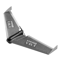
STEP 14: Trim the back face of the canopy out to allow the motor and
prop assembly to protrude from the back of the airframe. Cut to
within 1/8” of the edge so that the part remains strong. Do not cut on
the edge or the part will be too flimsy and may tear over time.
STEP 17: Use a sharp hobby knife to cut the holes and slots in the
equipment tray as marked in STEP 16. When you are done, the tray
should appear as illustrated.
TIP: If you are assembling a 600 “Performance” ARF, the hole in the back of the battery hatch must be large enough to accept the supplied Deans
Ultra connector.
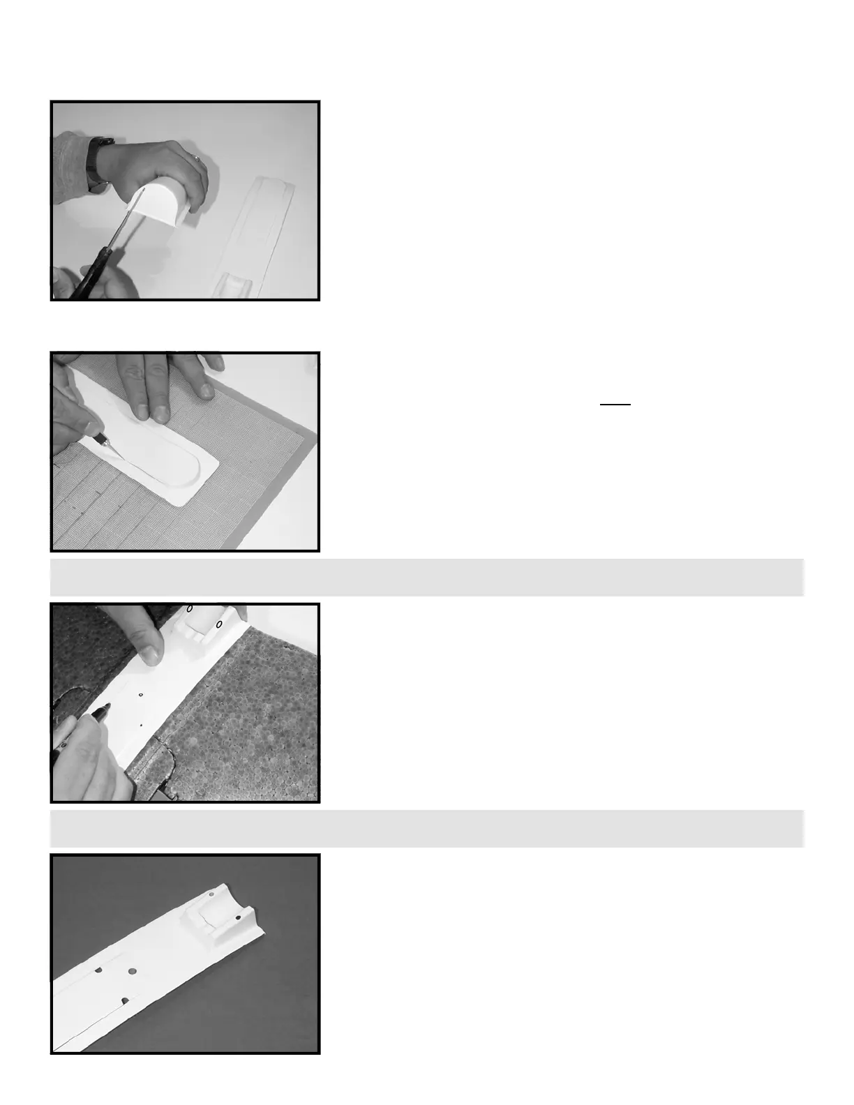
STEP 16: Position the equipment tray on the fuselage temporarily.
Using a fine tip marker, mark the following places on the tray as
illustrated:
• mark for two holes on the centers of both ledges of the motor
mount to accept the nylon tie that holds the motor to the tray.
• mark for one hole near the back center of the battery hatch to
allow for the battery wires to pass through from the ESC unit.
• mark for two slots on the outside edges of the battery hatch that
will allow for the servo wires to pass through from the battery
compartment to the receiver to be mounted on the top of the
battery hatch.
TIP: Electric drills and Dremel tools make cutting holes in the plastic parts much easier if you have access to them.
 Loading...