5
Operating instructions digital oval gear meter G
1.2.3 Measuring chamber
The measuring chamber is located in the centre of the meter.
In the measurement chamber there is an oval gear mechanism which rotates and results in electric
pulses being produced. These are then processed by the microprocessor on the electronic circuit
board.
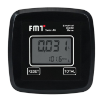
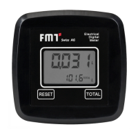
The microprocessor uses a calibration factor (i.e. a ‚weighting‘ assigned to each pulse) to convert the
pulses generated by the gears‘ revolutions into an intelligible value representing the volume of liquid
that has passed through. It is then displayed in the unit pre-set before in the corresponding registers of
the LCD display for partial and total volumes, respectively.
All our oval gear meters leave the factory with a default calibration factor = 1000 called „FACTORY
K FACTOR“. There is a possibility to ‚calibrate‘ the meter in order to adapt that factor to the physical
properties of dierent liquids.
However, there is always a possibility to return to the manufacturer‘s default setting.
1.2.4 Battery compartment
The meter is powered by two 1.5V standard batteries (N1).
The battery compartment is located within the meter housing. The housing lid must be removed in order
to replace the batteries.
1.3 Technical data
Designation Digital oval gear meter
Measuring system Oval gear
Resolution l/pulse 0,017
Flow rate range l/min 2 - 100
Operating pressure bar 3,5
Bursting pressure bar 28
Storage temperature °C -20 to +70
Storage humidity R.H. 95 %
Operating temperature (max.) °C 60
Flow rate loss at max. ow
(diesel oil) bar 0,2
Compatible liquids oil, diesel oil, self-lubricating low
viscosity liquids
Viscosity range cSt 2 - 2000
Accuracy (within ow rate range) ±0,5 %
Repeatability 0,2 %
Weight kg 0,65
Inlet / outlet threads 1“
Power supply (batteries) V 2 x 1,5
Lifetime of batteries (est.) h 14.000 - 30.000
Table 1-1:Technical data
 Loading...