10
US
Operating instructions - digital oval gear meter and pulse meter
Designation NUMERIxx³
DEF
23 190 870
Pulse meter
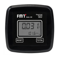
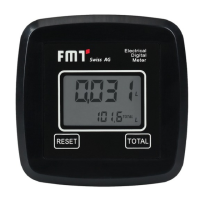
Oval gear meter
with display
DEF
23 829 870
Pulse meter
Oval gear meter
without display
DEF
23 823 006
23 823 066
Measuring system oval gear oval gear oval gear
Distance in-/out ange (inch) 3.74 3.74 3.74
Connection on both ends G 1‘‘ f G 1‘‘ f G 1‘‘ f
Media DEF DEF DEF
Flow capacity (gpm) 0.53-26.42 0.53-26.42 0.53-26.42
Pre-set ow direction horizontal horizontal horizontal
Permitted liquid temperature max. (°F) 95 95 95
Permitted ambient temperature (°F) 23 / 95 23 / 95 23 / 95
Measuring tolerance (%) 0,5 0,5 0,5
Nominal pressure (psi) 50 50 50
Burst pressure (psi) 400 400 400
Impulses (pulses/gal) 12.15 12.15
Contact form A-closer A-closer
Switching capacity (W) 10 10
Operating voltage (V) 3-30 V DC 3-30 V DC
Operating current (A) 0,5 0,5
Switch current (A) 0,5 0,5
Sensor resistor (mOhm) 300 300
Material housing stainless steel stainless steel stainless steel
External dimensions LxWxH (inch) 3.94 x 3.94 x 2.56 3.94 x 3.94 x 2.56 3.94 x 3.94 x 2.56
Weight (lb) 2.31 2.31 2.31
Tab. 4-2: Technical data oval gear meter DEF
5. Assembly
The oval gear meter comes pre-assembled and ready to go.
According to the version, accessories may be or must be mounted.
NOTE
Ensure cleanliness during installation and an exact connection and
accurate sealing.
6. Installation
The inlet and outlet of the oval gear meter are aligned in a straight axis and equipped with 1“ threads.
The meter may be installed in any given position, as a xed unit in a pipeline and/or as a mobile unit on a
spigot.
The oval gear meter does not have a pre-dened ow direction. Both ends may alternatively serve as
inlet or outlet, as needed. However, it is absolutely important that the side that is used as inlet (where the
pipeline arrives) is equipped with a lter with suitable performance characteristics. Solid particles getting
into the measuring chamber might clog up the ovar gear.
 Loading...