8
BASS INST/VOCAL switch – When this switch is engaged (INST mode), the
BASS controls act as a low frequency shelving EQ. When disengaged (VOCAL mode), the
BASS control acts as a low-mid band parametric EQ. (See the Guide To Equalisation onm
page 13 for more information on these terms.)
BASS FREQ – This control allows you to select which frequency you want the
BASS GAIN control to cut or boost from. In INST mode, the FREQ control selects values
in the range 25-400 Hz. In VOCAL mode, the FREQ control selects values in the range
50-800 Hz.
PRESENCE – This allows you to cut or boost hi mid frequencies (1.5 kHz). It offers
up to 12 dB of boost and 15 dB of cut. Boosting these hi mid frequencies adds presence to
the signal, allowing sounds to cut through the mix.
TREBLE GAIN - This shelving EQ allows you to cut or boost high frequencies by
+/- 14 dB. The frequency is switchable between two values using the INST/VOCAL
switch.
TREBLE INST/VOCAL switch – When this switch is engaged (INST mode),
the TREBLE GAIN control operates on frequencies above 3.3 kHz. When disengaged
(VOCAL mode), the TREBLE GAIN control operates on frequencies above 10 kHz.
EQ IN switch – When engaged, this illuminated switch makes the 3-BAND
EQUALISER section of the TrakMaster active. To bypass this section, leave the switch
disengaged.
OUTPUT LEVEL
OUTPUT LEVEL meter – This meter shows the level of the signal leaving the
TrakMaster. You should aim for the meter to peak at the 0 LED, without illuminating the
O/L (overload) LED. It is especially important not to overload the output when using the
optional digital output, as this will cause severe and unpleasant distortion, even if
overloading is brief.
FADER - This is used to match the output volume level from the TrakMaster to the
input level of the next unit in the chain (e.g. sound card, hard disk recorder, tape machine,
mixer etc.) When setting the output level, always start with this control set fully anti-
clockwise and increase the output level until you reach the correct level – do not start with
the FADER set high, as it may damage the next unit in the chain.
If inserting the TrakMaster into a channel of a mixing console, set the FADER at 0
(roughly its 3 o’clock position), and adjust the levels using the console.
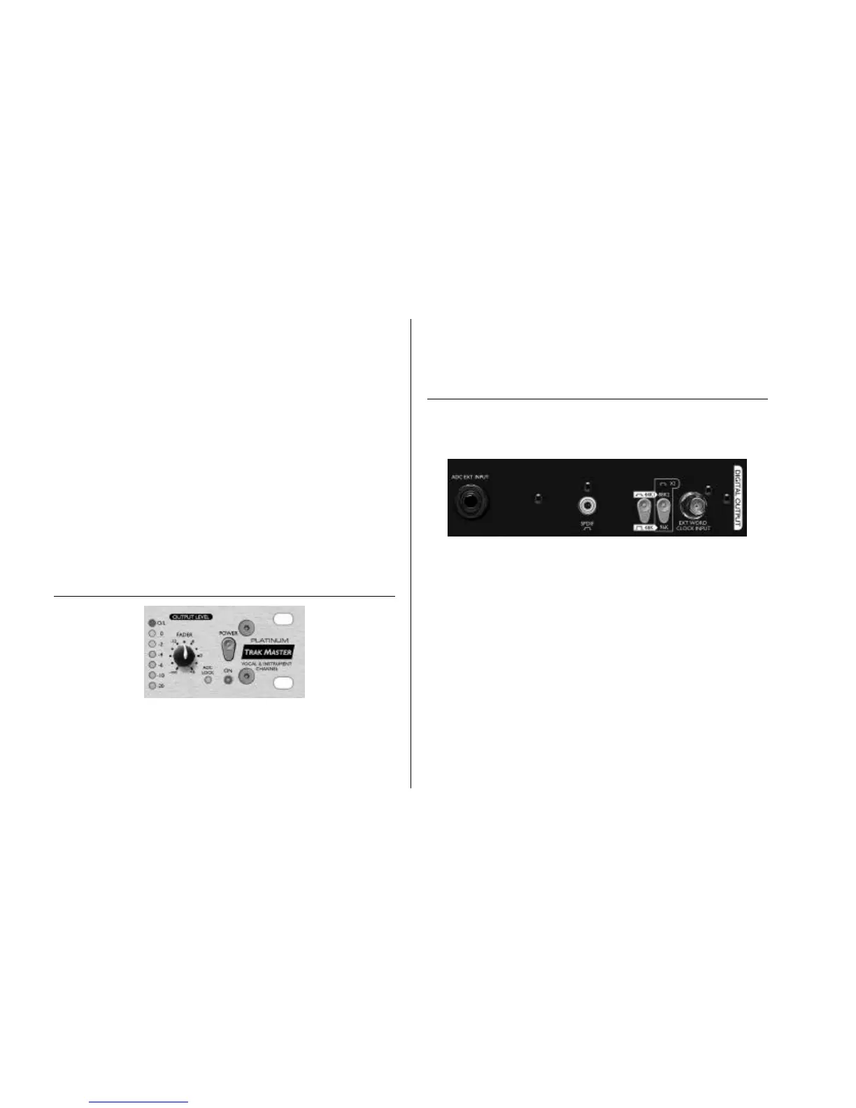
DIGITAL OUTPUT
In addition to the analogue outputs, a high quality 24 bit, 128 times oversampled digital
output may be fitted as an option, which can operate at sample frequencies of 44.1, 48,
88.2 or 96 kHz. All of the following functions are available on the rear panel when this
option is fitted:
ADC EXT INPUT (rear panel) – This line level input on the rear panel allows
an additional signal to be routed through the spare channel of the stereo digital output.
SPDIF OUTPUT - This 24 bit output is SPDIF format on an RCA phono
connector. If 16 bit resolution is required, the receiving device should dither the 24 bit
signal to achieve 16 bit performance.
SAMPLE FREQUENCY - Two switches give a choice of four sample frequencies
as marked on the rear panel. The left hand switch selects between 44.1kHz (switch out)
and 48kHz (switch in), and the right hand switch doubles the selected frequency.
EXTERNAL WORDCLOCK - If an external wordclock source is fed to the BNC
connector, the TrakMaster will attempt to synchronise to it. When the unit is correctly
locked to the external clock source the ADC LOCK LED (on the front panel) will light to
indicate correct operation. In this case the ADC LOCK LED should be continuously lit. If
this flickers it indicates bad jitter on the synchronising signal which would need
investigation of the wordclock generating device.