8
O
n
1
2
3
4
7
5
6
8
4
4
.
.
2
2
A
A
l
l
p
p
h
h
a
a
5
5
4
4
0
0
&
&
5
5
6
6
0
0
M
M
o
o
d
d
e
e
l
l
s
s
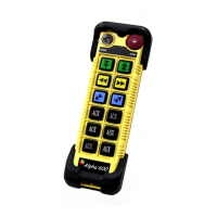
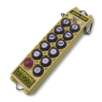
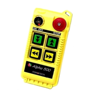
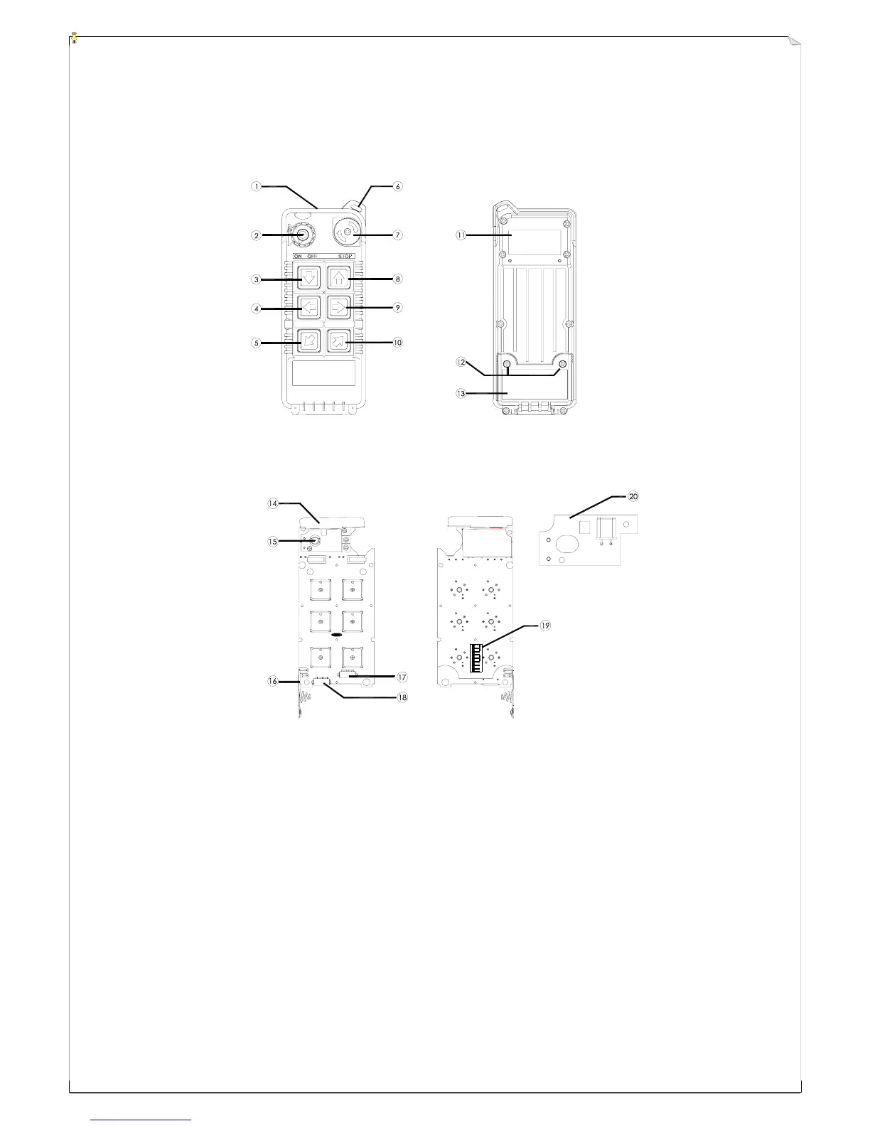
(Fig. 5) Front View (Fig. 6) Back View
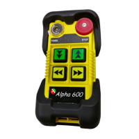
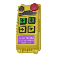
(Fig.7) Front View (Fig. 8) Back View
1) Transmitter enclosure 8) Pushbutton #1 (↑ / Up) 15) Status LED display
2) Power switch (ON/OFF) 9) Pushbutton #3 (→ / East) 16) Battery contact
3) Pushbutton #2 (↓ / Down) 10) Pushbutton #5 (↗ / North) 17) AUX micro-button connector*
4) Pushbutton #4 (← / West) 11) System information 18) Programming port
5) Pushbutton #6 (↙ / South) 12) Battery cover screws 19) ID code dip-switch
6) Wrist strap attachment 13) Battery cover 20) Transmitting RF board
7) Emergency stop (EMS) 14) Internal antenna
* For Alpha 540A and Alpha 560A models only.