9
1
2
3
4
5
6
7
8
10
17
18
16
9
11
12
13
14
15
20
21
22
23
24
25
19
4
4
.
.
3
3
A
A
l
l
p
p
h
h
a
a
5
5
8
8
0
0
M
M
o
o
d
d
e
e
l
l
s
s
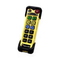
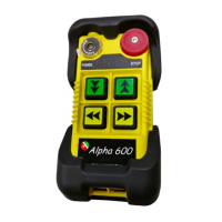
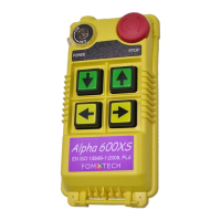
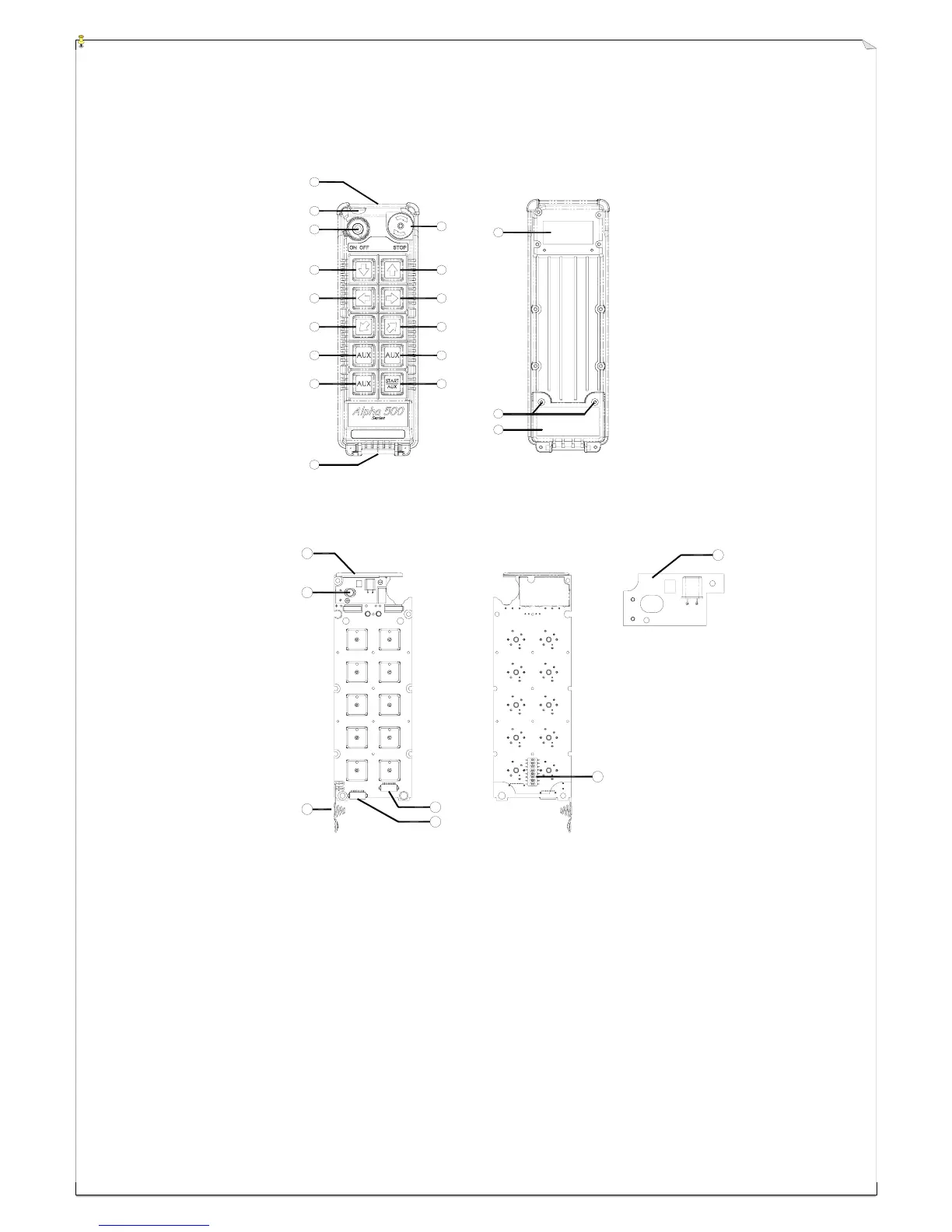
(Fig. 9) Front View (Fig. 10) Back View
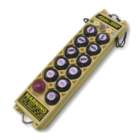
(Fig. 11) Front View (Fig. 12) Back View
1) Transmitter enclosure 9) Waist belt attachment 17) Battery cover screws
2) External antenna port 10) Emergency stop (EMS) 18) Battery cover
3) Power switch (ON/OFF) 11) Pushbutton #1 (↑ / Up) 19) Internal antenna
4) Pushbutton #2 (↓ / Down) 12) Pushbutton #3 (→ / East) 20) Status LED display
5) Pushbutton #4 (← / West) 13) Pushbutton #5 (↗ / North) 21) Battery contact
6) Pushbutton #6 (↙ / South) 14) Pushbutton #7 (A1) 22) AUX micro-button connector*
7) Pushbutton #8 (A2) 15) Pushbutton #9 (A3) 23) Programming port
8) Pushbutton #10 (A4) 16) System information 24) ID code dip-switch
25) Transmitting RF board
* For optional AUX micro-button or buttons.