- 31 -
7
7
.
.
R
R
E
E
C
C
E
E
I
I
V
V
E
E
R
R
S
S
E
E
T
T
T
T
I
I
N
N
G
G
S
S
7
7
.
.
1
1
H
H
o
o
w
w
t
t
o
o
S
S
e
e
t
t
α
α
6
6
0
0
4
4
/
/
6
6
0
0
7
7
/
/
6
6
0
0
8
8
/
/
6
6
1
1
2
2
R
R
e
e
c
c
e
e
i
i
v
v
e
e
r
r
I
I
D
D
C
C
o
o
d
d
e
e
s
s
7
7
.
.
1
1
.
.
1
1
H
H
o
o
w
w
t
t
o
o
S
S
e
e
t
t
α
α
6
6
0
0
4
4
/
/
6
6
0
0
7
7
/
/
6
6
0
0
8
8
R
R
e
e
c
c
e
e
i
i
v
v
e
e
r
r
I
I
D
D
C
C
o
o
d
d
e
e
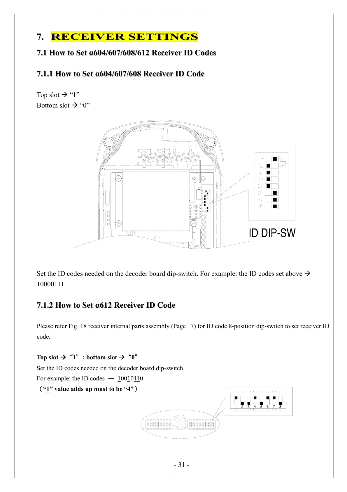
Top slot “1”
Bottom slot “0”
ID DIP-SW
Set the ID codes needed on the decoder board dip-switch. For example: the ID codes set above
10000111.
7
7
.
.
1
1
.
.
2
2
H
H
o
o
w
w
t
t
o
o
S
S
e
e
t
t
α
α
6
6
1
1
2
2
R
R
e
e
c
c
e
e
i
i
v
v
e
e
r
r
I
I
D
D
C
C
o
o
d
d
e
e
Please refer Fig. 18 receiver internal parts assembly (Page 17) for ID code 8-position dip-switch to set receiver ID
code.
Top slot “1"; bottom slot “0"
Set the ID codes needed on the decoder board dip-switch.
For example: the ID codes → 1
0010110
(“1
” value adds up must to be “4”)
12345678