5
TECHNICAL MANUAL FOR INSTALLATION, USE AND MAINTENANCE
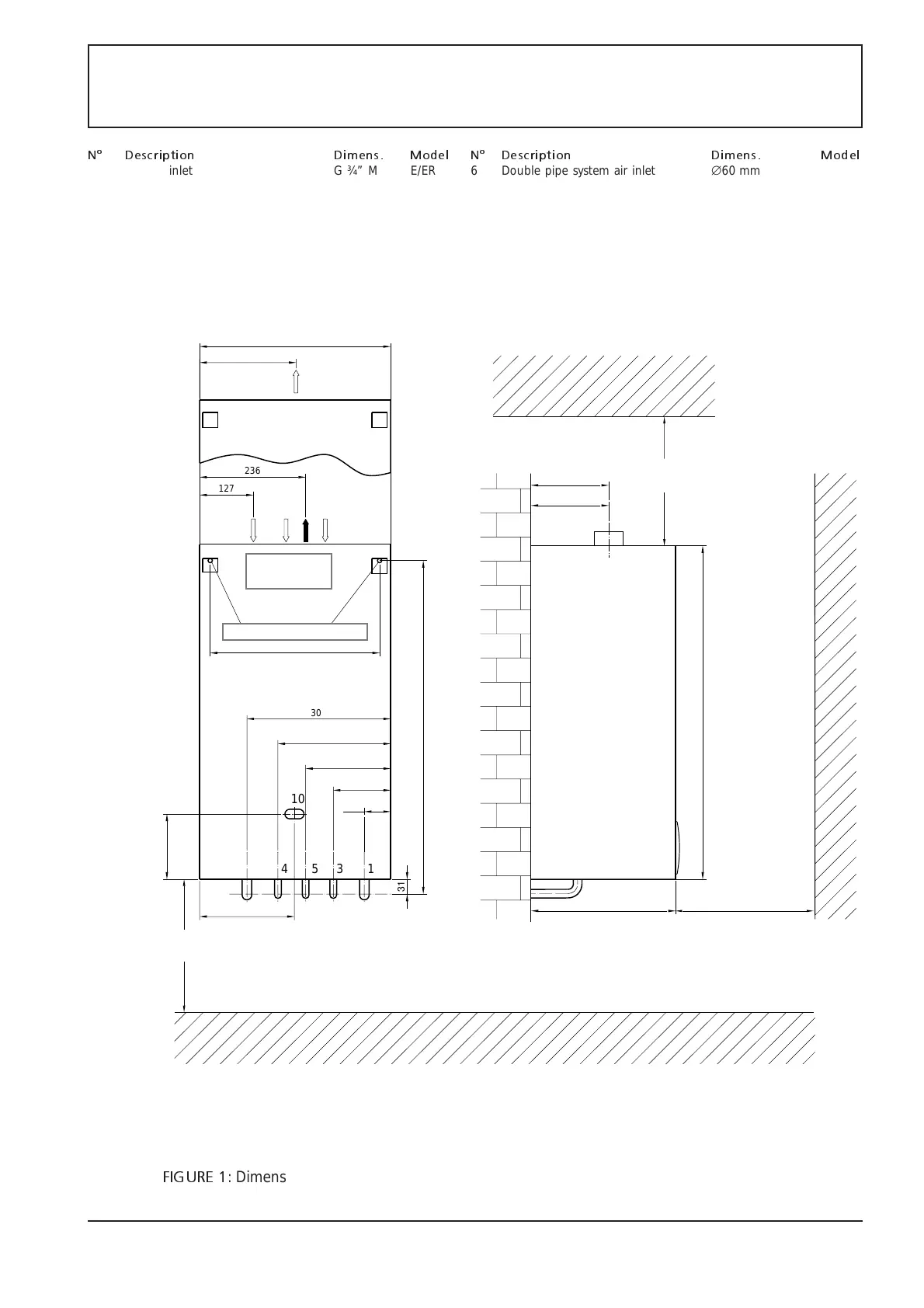
FIGURE 1
: Dimensions, free distance to be maintained, hydraulic connections, air inlet and flue
exhaust connection.
2
9
Mod. E
MIN 50 cm
MIN 35 cm
6 878
Fori per tassello Ø14
1534
10
301
120
178
236
55
700
300
Mod. ER
MIN 40 cm
355
400
215
137
700
200
185 mod.E
159 mod.ER
Uscite e
scarico fumi
31
127
236
N° Description Dimens. Model N° Description Dimens. Model
1 System inlet G ¾” M E/ER 6 Double pipe system air inlet ∅60 mm ER
2 System flow G ¾” M E/ER 7 Double pipe system flue exhaust ∅60 mm ER
3 Water network G ¾” M E/ER 8 Double pipe system flue inlet/exhaust∅100/ ∅60 mm ER
4 Hot Water G ¾” M E/ER 9 flue exhaust ∅130 mm E
5 Gas G ¾” M E/ER 10 Space for electric cables 20x40 E/ER
air inlet and
flue discharge
holes for screw anchors Ø14