12
TECHNICAL MANUAL FOR INSTALLATION, USE AND MAINTENANCE
Q 02'(//2 23(5$7,216
1 ER Remove the front panel of the sealed chamber by loosening its screws.
1 E --
2 ER Remove the combustion chamber front panel.
2 E --
3 E, ER Remove the burner assembly from nozze-holder manifold.
4 E, ER Replace tha nozzles and copper seals with the parts included in the kit.
5 E,ER Re-install the burner.
Q
*DVYDOYH
23(5$7,216
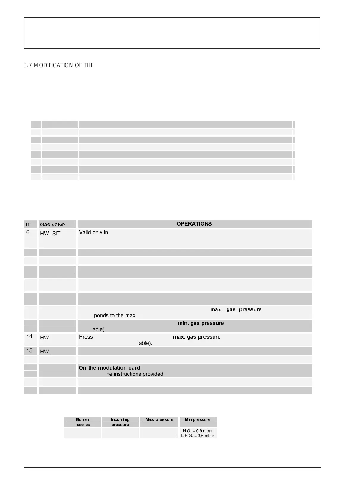
6
HW, SIT
Valid only in countries where the network gas is supplyed at two pressures: install or remove the
diaphragm located between the discharge pipe and the gas valve (it is included in the kit, when
needed).
7
HW, SIT
Select the gas type on the modulation card by moving the jumper J7 (Fig.8)
8
HW, SIT
Remove the modulator cover
9
HW, SIT
Loosen the plug from the gas valve pressure inlet and check the incoming pressure with a
pressure gauge (see table below). Check the values when the boiler is working.
10
HW, SIT
Re-install the plug on the pressure inlet, open the gas valve outlet and connect the pressure
gauge to it.
11
HW, SIT
Turn the screw/adjustment nut counter-clockwise by 2 revs; turn the electrical system and the
heating system on; the flame on the main burner lights.
12
SIT
Check the pressure gauge value and adjust the
PD[ JDV SUHVVXUH
screw; this value
corresponds to the max. burner power (see table).
13
HW, SIT
Disconnect the modulator and adjust the
PLQ JDVSUHVVXUH
by turning the corresponding screw
(see table)
14
HW
Press the modulator tip and adjust the
PD[JDVSUHVVXUH
screw; this value corresponds to the
max. burner power (see table).
15
HW, SIT
Re-connect the modulator and check the set pressure values.
16
HW, SIT
Re-install the cap and seal the adjustment screws (e.g. with a drop of paint).
17
HW, SIT
2QWKH PRGXODW LRQF D UG
move the jumper J16 (Fig.4) to enable the parameter change mode
and follow the instructions provided under section 3.6.
18
HW, SIT
Disconnect the pressure gauge and place the plug on the pressure outlet.
19
HW, SIT
Place the METHANE (N.G.) or L.P.G. stickers near the gas valve and rating plate.
%XUQHU
QR]]OHV
,QFRPLQJ
SUHVVXUH
0D[SUHVVXUH 0LQSUHVVXUH
N.G. = 1,30 mm
L.P.G. = 0,75 mm
N.G. = 20,0 mbar
L.P.G.= 37,0 mbar
N.G. = 10,0 mbar
L.P.G. = 35,0 mbar
N.G. = 0,9 mbar
L.P.G. = 3,6 mbar
3.7 MODIFICATION OF THE BOILER PRESET GAS
This modification must be carried out ONLY by the Service Centre or authorised technicians using the components
included in the special kit.
The following procedure can be adopted when setting the boiler for LPG (with the LPG kit) or METHANE (with the
METHANE kit).
The following operations differ in accordance to the gas valve (HW=Honeywell; SIT= SIT La Precisa)