6
TECHNICAL MANUAL FOR INSTALLATION, USE AND MAINTENANCE
wall
boiler
3.2 WATER AND COMBUSTIBLE SYSTEM
The equipment has been designed for the type of
combustible gas specified on the plate located inside the
shell. Make sure that the available gas type and the gas
specified on the equipment match.
The combustible supply piping and the control system must
be perfectly sealed and their sections must be suitable for
the equipment capacity.
If L.P.G. is supplied, make sure that the second-stage
pressure reducer located on the tank-boiler line has a min.
capacity of 4 kg/h and 37 mbar (column of water 370)
outlet pressure adjustment.
The original gas preset of the boiler can be changed by
replacing the gas nozzles and re-calibrating the gas valve
minimum pressure.
This operation must be carried out by
qualified
technicians
: contact the authorised Service Centre.
The Service Centre must verify the correct operation of
the equipment and officially validate the guarantee
certificate within 8 days from installation.
For newly-designed water systems, Fig. 1 shows the piping
layout when looking at the wall.
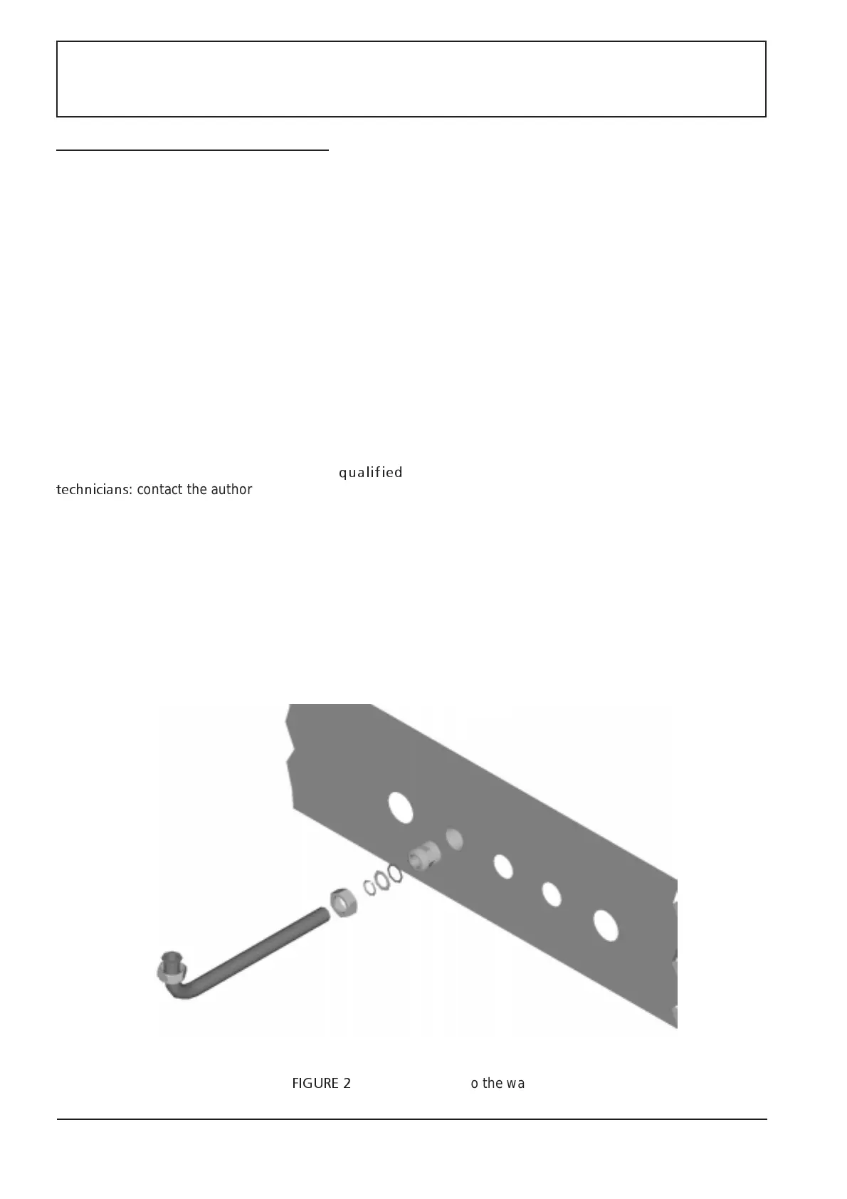
Fig. 2 shows how to connect pipes to the wall.
Place the wall mounting jig (delivered with the boiler) on
the wall to define the correct location of screw anchors
and pipes.
The pressure of the water coming from the water system
must be kept under control and below the limit specified
on the equipment plate, on the inlet point.
Hence the need for a pressure reducing valve on the
equipment cold water pipe.
The circulation device, at speed III, is suitable for the
majority of the systems. In single-pipe or very large systems,
when the load loss is remarkable or when all radiators are
not equally supplied, the circulation of water can be
increased by installing an additional pump or replacing the
pump supplied with the boiler with an expanded circulation
device.
See fig. 3 for available head/flow rate curves of the heating
system.
The boiler is equipped with a 7 litres storage tank which is
suitable for standard heating system. Specific solutions are
needed for larger or vertical systems.
The standard equipment does not include an automatic
by-pass valve between the supply and return system.
A special automatic by-pass valve is needed when
thermostatic valves are installed on all radiators or when
local flow stopping valves are mounted.
FIGURE 2
: Pipes connection to the wall