10
TECHNICAL MANUAL FOR INSTALLATION, USE AND MAINTENANCE
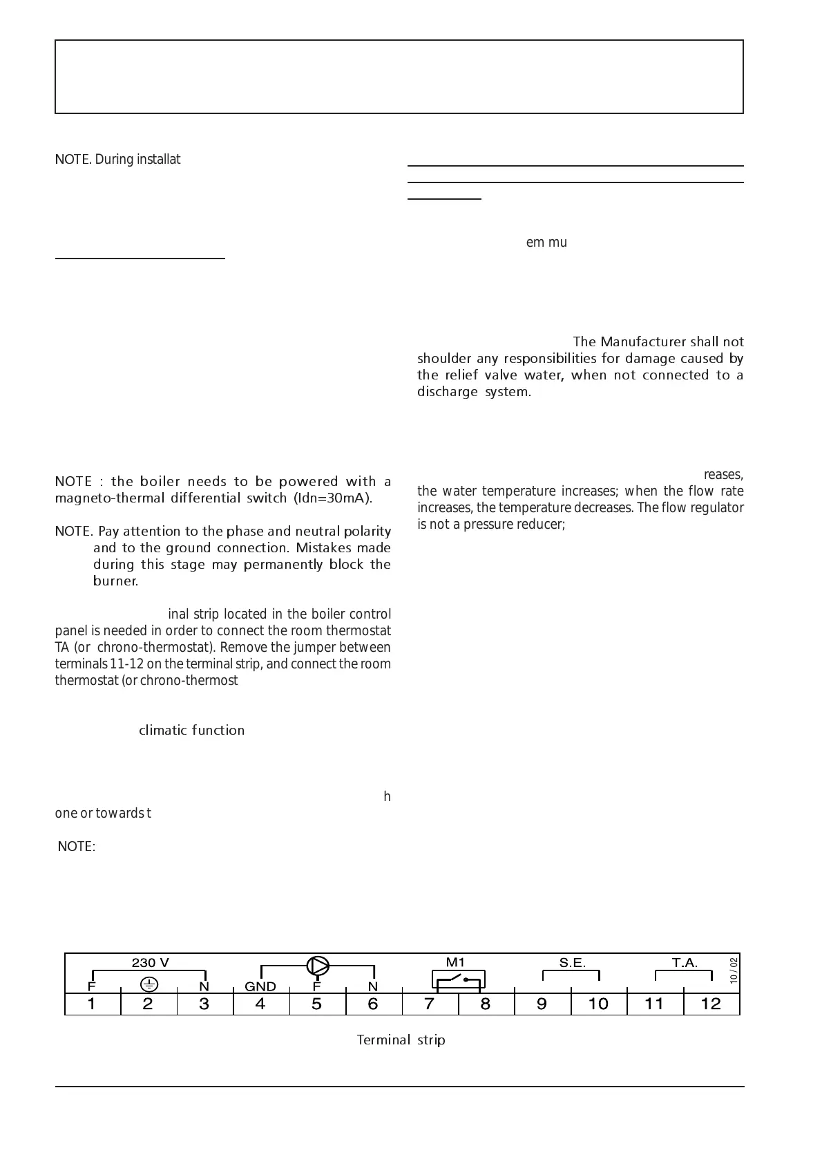
Terminal strip
NOTE
. During installation, make sure that the fumes cannot
go back into the equipment near terminal pieces or
joints between various pipe sections. When no seals
are provided, apply some silicon between two pipes.
3.4.ELECTRICAL SYSTEM.
Make sure that the available AC power matches the power
specified on the equipment rating plate (230VAC FN 50Hz).
Check the grounding line and connect it to the boiler. The
manufacturer shall not shoulder any responsibilities for
damage caused by lack of compliance with this
requirement.
De-energise the equipment and connect it to the electrical
system. For the electrical connection, use the terminal strip
located in the control panel and pay attention to the
indicated electrical connections. Remove the shell and the
control panel cover to access the terminal strip.
NOTE : the boiler needs to be powered with a
magneto-thermal differential switch (Idn=30mA).
NOTE. Pay attention to the phase and neutral polarity
and to the ground connection. Mistakes made
during this stage may permanently block the
burner.
Access to the terminal strip located in the boiler control
panel is needed in order to connect the room thermostat
TA (or chrono-thermostat). Remove the jumper between
terminals 11-12 on the terminal strip, and connect the room
thermostat (or chrono-thermostat).
Flow water temperature is adjusted in accordance to the
outdoor one (
climatic function
). In order to do so, it is
necessary to mount an outdoor probe (SE), available as
optional an option. Use connector 9-10 on the connecting
strip to connect the probe. Place it on the outside, north
wall of the building, do not absolutely place it on the south
one or towards the sun.
NOTE:
separate electric cables from power and signal ones
(TA, SE) and install them inside separates pipes.
3.5.INFORMATION TO BE RESPECTED BEFORE AND
DURING THE INSTALLATION OF THE EQUIPMENT ON
THE WALL.
- The heating system, and radiators in particular, and the
sanitary water system must be thoroughly washed with
water and a detergent-degreaser;
- Make sure the external systems are connected to the
correct boiler pipes. Ensure that all pipe connections are
correct.
- The relief valve inside the boiler must be connected to a
dedicated discharge pipe.
The Manufacturer shall not
shoulder any responsibilities for damage caused by
the relief valve water, when not connected to a
discharge system.
- When the equipment is installed under the heating system
units, on-off valves should be installed between the system
and the boiler, thus facilitating maintenance activities.
- The sanitary water flow rate must be adjusted (on the
flow meter, no.19 Fig.7): when the flow rate decreases,
the water temperature increases; when the flow rate
increases, the temperature decreases. The flow regulator
is not a pressure reducer; therefore, if the water system
pressure is too high, external pressure reducers must be
installed.
- Make sure that the free space and distances
recommended in this manual are respected, to facilitate
maintenance activities.
- Make sure that the fume discharge pipe, the chimney
and carburant air supply system are clean and efficient.
- With reference to forced-flow equipment, make sure that
no other fume discharge pipes are connected to the
chimney, with the only exception of chimneys for sealed-
chamber boilers.
- Make sure that condensation and rain water in the fume
and air pipes are collected and discharged and do not
reach the boiler.
- Connect the air intake and fume discharge pipes; make
sure that they are stable, but removable; they must not
be loose and their sealing over time must be guaranteed.