9
TECHNICAL MANUAL FOR INSTALLATION, USE AND MAINTENANCE
carburant air route R = aerodynamic resistance of a plain pipe route
flue route Rtot = total aerodynamic resistance of the pipes inside the air-flue route
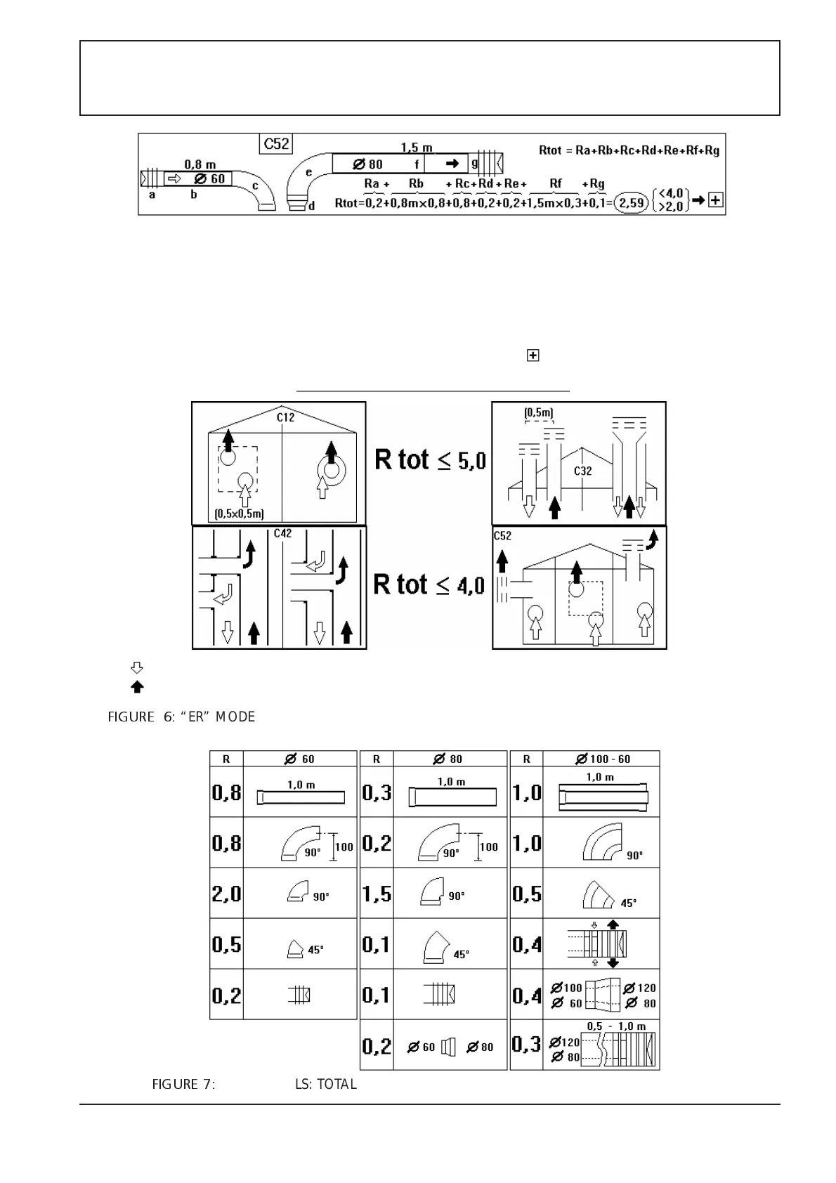
EXAMPLE. Boiler X ER.
1) Selected air-fume system: double pipe C52.
2) Total path length: air (a) wind-proof head + (b) 0.8m
straight + (c) 90° bend; fumes (e) 90° bend + (f) 1.5m
straight, (g) wind-proof-head.
3) If ø60mm for air and ø80mm for fumes, R for the various
sections is: Ra=0.2, Rb=0.8x0.8=0.64, Rc=0.8, Re=0.2,
Rf=1.5x0.3=4.5, Rg=0,1; for ø80 fume pipe, the (d)
60-80 reducer section is needed, resistance: Rd=0,2.
4) Rtot=0.2+0.64+0.8+0.2+0.2+0.45+0.1=2.59
5) Rtot=2.59 is good for C52 because it is lower than 4.0.
6) According to the table, the diaphragm is not needed
because Rtot is higher than 2.0, but the shutter must be
moved to the position
C12 = horizontal air
and flue pipes
system. Intake and
discharge areas are
very close and
under the same
wind conditions.
C32 = vertical air-
flue pipes. Intake
and discharge
areas are very
close and under the
same wind
conditions.
C42 = the air-flue
intake and
discharge system
are made through
the connection to
two collective and
separate pipes; one
for the air and the
other for the flues .
C52 = double pipe
air-flue system: one
for the air and the
other for the flues
which flow into
different pressure
FIGURE 6:
“ER” MODELS : Rtot TOTAL MAXIMUM ALLOWED AERODYNAMIC RESISTANCE OF THE PIPES
INSIDEW THE DIFFERENT AIR INTAKE AND FLUE DISCHARGE SYSTEMS
FIGURE 7:
“ER” MODELS: TOTAL AERODYNAMIC RESICETENCE OF SOME PIPES SECTIONS