8
TECHNICAL MANUAL FOR INSTALLATION, USE AND MAINTENANCE
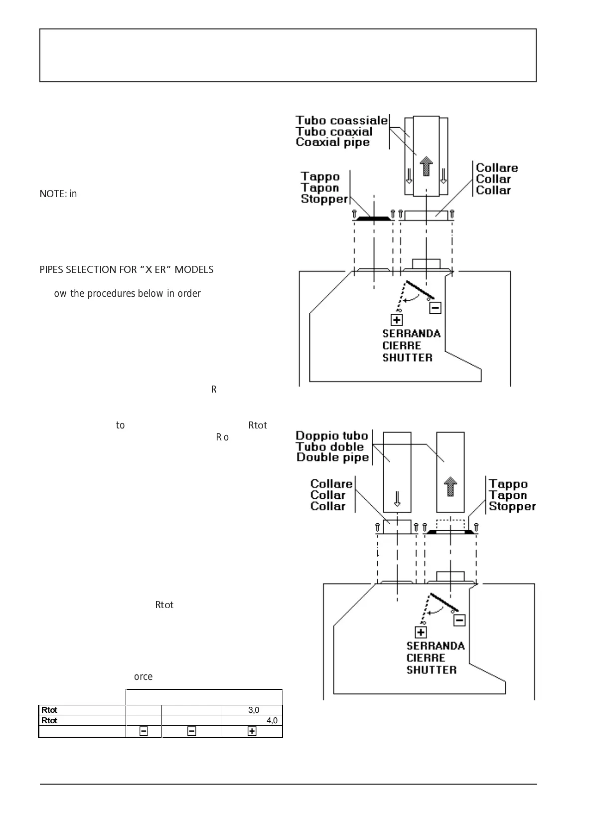
FIGURE 5
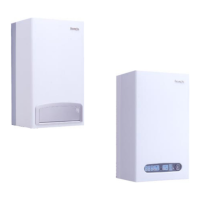
FIGURE 4
Seal chamber devices are manufactured for air intake and
flue discharge(Ø100-Ø60) coaxial systems; however it is
possible to realize some double pipe systems with separate
air intake (Ø60) and flue discharge pipes (Ø60); in order to
do so it is necessary to replace the cap and the collar
described on picture 4 with those of picture 5, these latter
are supplied with the boiler itself.
NOTE
: inside the lower sealed part of the boiler, inside the
metal casing, there is a 3mm hole which helps keeping
the pressure inside the boiler lower than the room one. In
this way, gas escapes are in-taken inside the combustion
chamber and they are not released into the room.
PIPES SELECTION FOR X ER MODELS
Follow the procedures below in order to realize a proper
pipe selection:
1) Select one of the four air-flue systems, in compliance
with current regulation, as per Fig.6 (C12, C32, C42,
C52).
2) Measure the total path length of air and flue pipes.
3) Select the air-flue pipe diameter/s and refer to Fig.6 to
define the aerodynamic resistance
R
for each pipe
section
4) Calculate the total aerodynamic resistance
Rtot
by
adding up the aerodynamic resistance R of air and flue
pipes.
5) Compare the calculated Rtot value with the max. value
specified in fig.5 for the selected air-flue system. The
calculated value should be equal to or lower than the
value specified in fig.5. Should this not be then case,
increase the pipe diameter and repeat the test starting
from point 3 above.
6) After passing the above mentioned test, establish how
to set the shutter. The cross reference table below
specifies the shutter setting depending on the type of
air-flue system (coaxial or double pipe),boiler type, total
aerodynamic resistence
Rtot
of the air-flue path.
Sealed chamber with forced draught:
;(5
5WRW
systems C12-C32 till 2,0 From 2,0 a 3,0 From 3,0 a 5,0
5WRW
systems C42-C52 till 1,0 From 1,0 a 2,0 From 2,0 a 4,0
Shutter setting