13
TECHNICAL MANUAL FOR INSTALLATION, USE AND MAINTENANCE
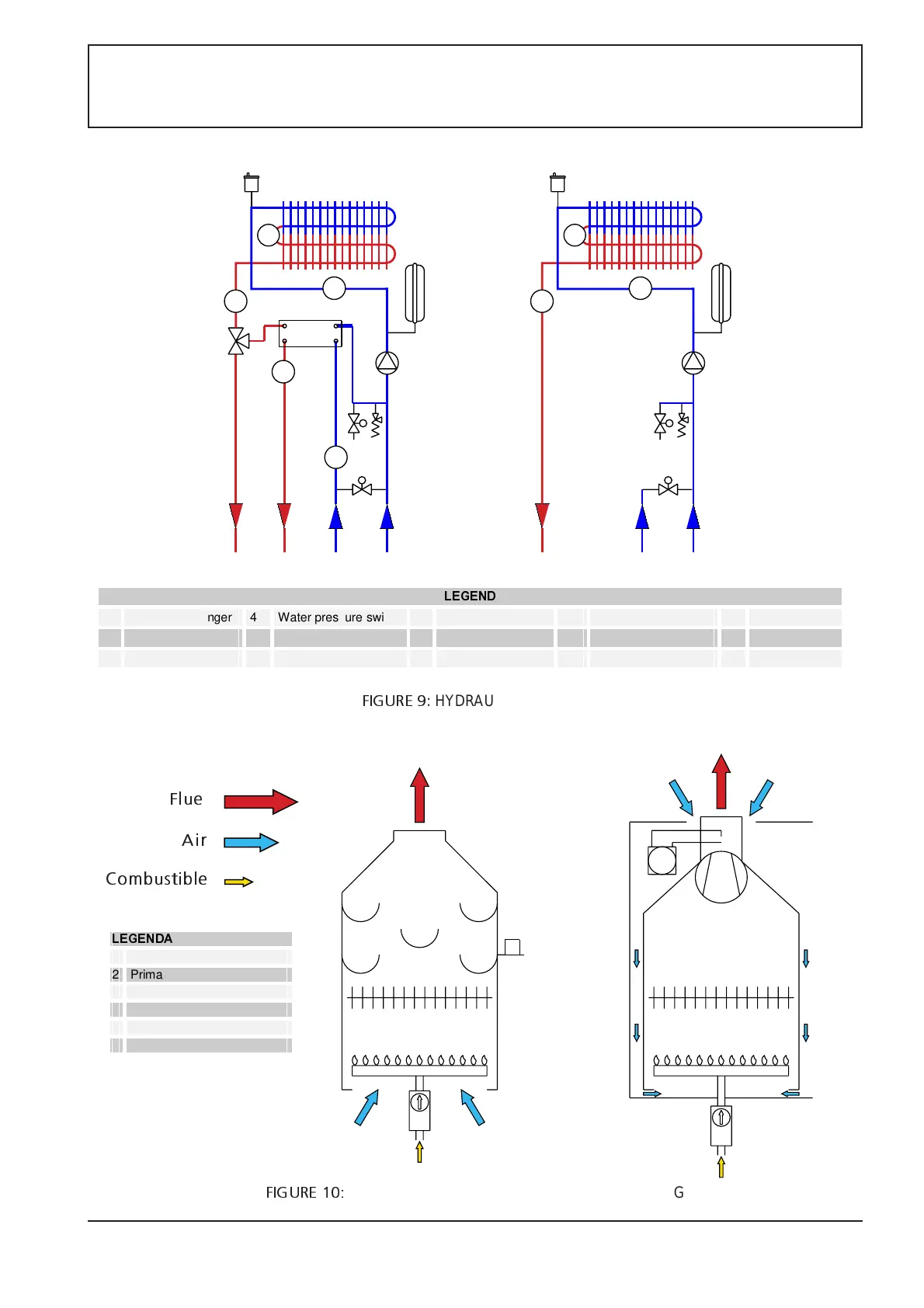
FIGURE 9
: HYDRAULIC DRAWINGS
P
T
11
22
33
4
5
6
/(*(1'$
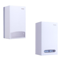
1 Burner
2 Primary exchanger
3 Valvola gas
4 smokes thermostat
5 Air pressare switch
6 Fan
11
14
12
2
11
F
33
44
55
66
77
8
9
8
9
1010
H
T˚
T˚
P
2
13
H
T˚
P
system
flow
hot
water
water
network
system
inlet
system
flow
water
network
system
inlet
Flue
Combustible
Air
/(*(1'
1 Primary exchanger 4 Water pressure switch 7 Flow probe 10 Filling tap 13 Sanitary probe
2 Pump 5 Safety thermostat . 8 Safety Relief valve . 11 Diverting valve 14 Flow switch
3 Expansion vessel 6 Air vents 9 Outlet valve 12 Sanitary exchanger.
FIGURE 10:
COMBUSTIBLE, AIR AND FLUE CIRCUIT DRAWING