- 7 -
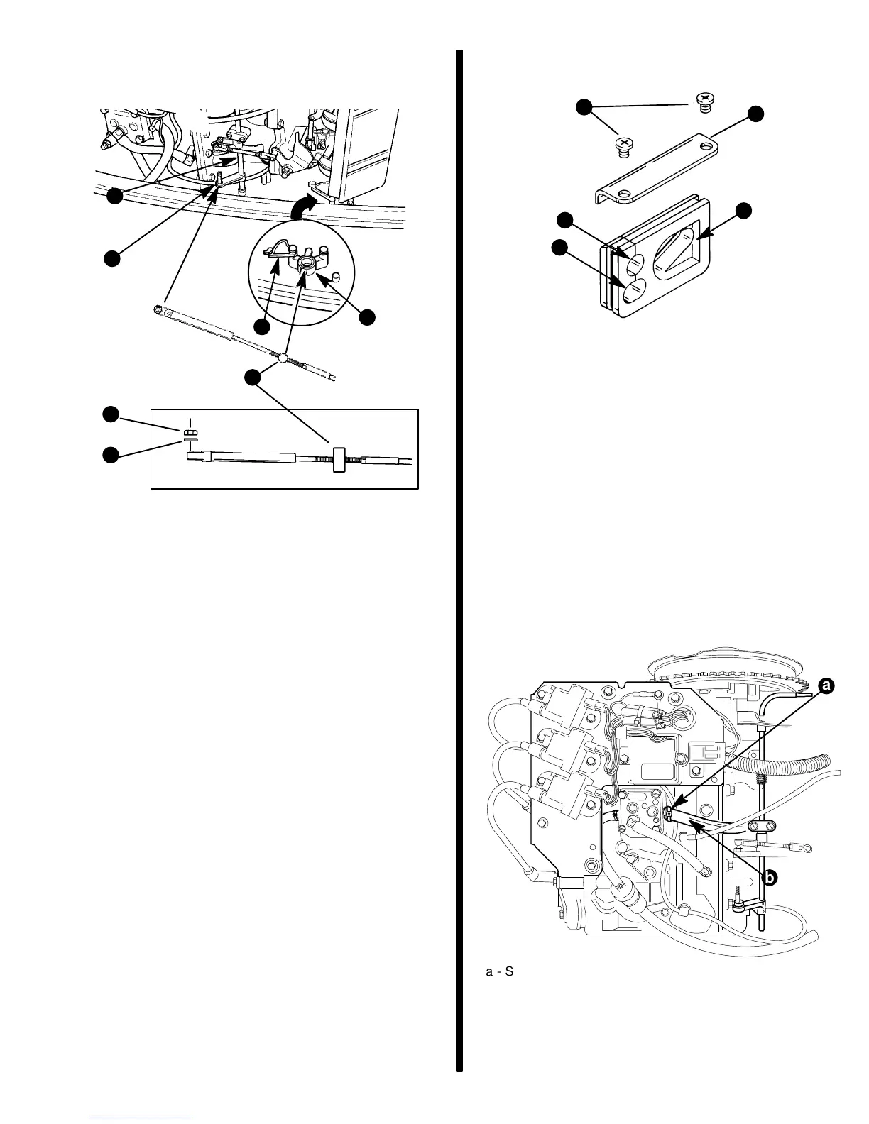
NOTE: There should be some preload on throttle
cable to ensure throttle will return to full idle when in
neutral.
d
e
b
a
c
f
g
a - Barrel Retainer
b - Throttle Cable Mounting Stud
c - Cable Barrel
d - Locknut
e - Nylon Washer
f - Throttle Shaft
g - Barrel Retainer Latch
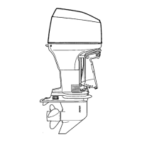
7. Route throttle cable through grommet opening
(a).
8. Route power trim wire harness through grommet
opening (b).
9. Install grommet in bottom cowl. Secure with re-
tainer (e) and screws (d).
Starboard
Bottom Cowl Grommet
d
e
c
a
b
a - Opening for Power Trim Wire Harness
b - Opening for Throttle Cable
c - Opening for Fuel Connector
d - Screws
e - Retainer
Fuel Line Installation
Fuel Line
Minimum fuel line inside diameter (I.D.) is 5/16 in. (8
mm) with separate fuel line/fuel tank pickup for each
engine.
1. Install fuel line on fuel pump, secure with a sta-
strap (a).
a
b
a - Sta-Strap
b - Inlet Fuel Line
2. Insert fuel connector into bottom cowl grommet.
Install bolt and tighten securely.