- 4 -
!
WARNING
Before operating, outboard(s) MUST BE SE-
CURED to boat transom with four 1/2 in. diameter
bolts, flat washers and locknuts (supplied) as fol-
lows: two (2) bolts must be installed thru upper
mounting holes and two (2) bolts thru lower
mounting holes. Installation must be water-tight
and outboard should be checked for tightness on
transom during operation. Failure to bolt out-
board to transom as described may result in dam-
age to the boat and/or loss of outboard and possi-
ble injury to occupants of boat.
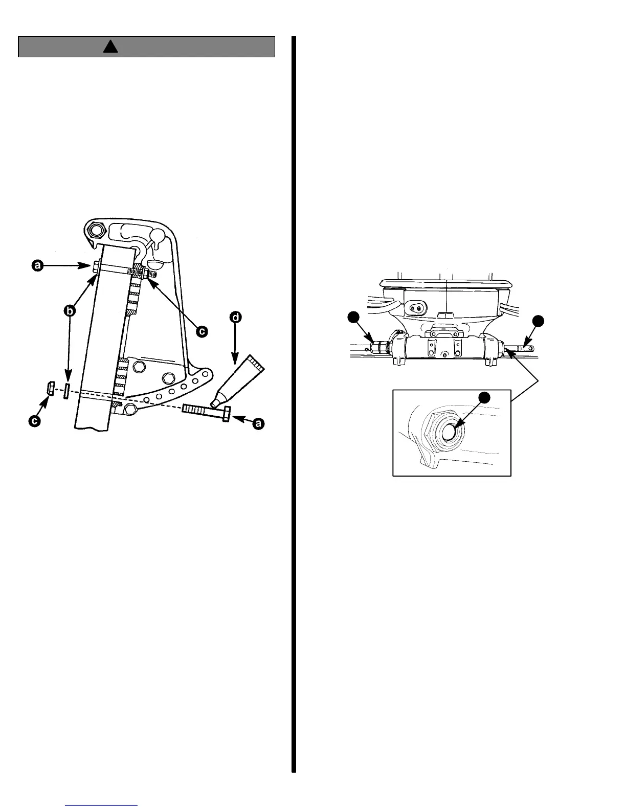
a - 1/2 Inch Diameter Bolts
b - Flat Washers
c - Locknuts
d - Marine Sealer
Ride Guide Steering Cable/
Attaching Kit Installation
NOTE: These instructions are for single cable-single
outboard installations. Instructions for mounting dual
engines are included with the applicable dual engine
attaching kit. Refer to “Quicksilver Accessories
Guide” to determine correct kit.
Refer to “Quicksilver Accessories Guide” to deter-
mine correct length of steering cable.
IMPORTANT: Steering cable must be correct
length. Sharp bends on too-short of a cable result
in “kinks;” too-long of a cable requires unneces-
sary bends and/or loops. Both conditions place
extra stress on the cable.
Install steering mount and steering wheel in accor-
dance with installation instructions that accompany
each.
Installing Ride Guide Steering Cable
To The Outboard
IMPORTANT: Before installing steering cable in
tilt tube, lubricate entire cable end with Quicksil-
ver 2-4-C Marine Lubricant.
NOTE: Ride Guide steering cable is lubricated at the
factory and requires no additional lubrication at initial
installation.
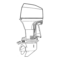
1. Lubricate seal (a) inside of outboard tilt tube and
entire cable end (b) with Quicksilver 2-4-C Marine
Lubricant.
2. Insert steering cable end thru outboard tilt tube
and secure steering cable to tilt tube with steering
cable attaching nut (c), as shown. Torque nut to
35 lb. ft. (47.5 N·m).
a
c
b
Steering Link Rod Installation
IMPORTANT: The steering link rod that connects
the steering cable to the engine must be fastened
using special washer head bolt (“a” – Part Num-
ber 10-14000) and self locking nuts (“b” & “c” –
Part Number 11-34863). These locknuts must
never be replaced with common nuts (non lock-
ing) as they will work loose and vibrate off freeing
the link rod to disengage.
IMPORTANT: Disengagement of a steering link
rod can result in the boat taking a full, sudden,
sharp turn. This potentially violent action can
cause occupants to be thrown overboard expos-
ing them to serious injury or death.
3. Assemble steering link rod to steering cable with
two flat washers (d) and nylon insert locknut (“b”
– Part Number 11-34863). Tighten locknut (b) un-
til it seats, then back nut off 1/4 turn.