Paragraphs 20-21
12
7 13 14
FORD
14
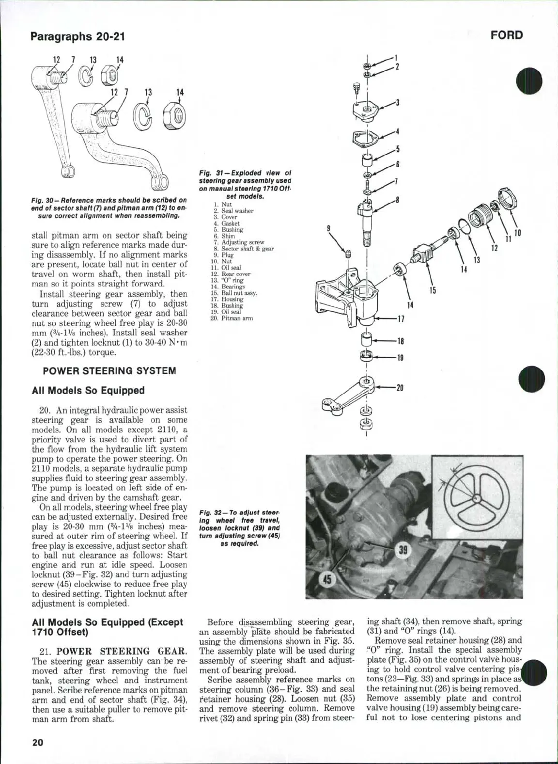
Fig.
30—
Reference marks should be scribed on
end of sector shaft
(7}
and pitman
arm (12)
to en-
sure correct alignment when reassembling.
stall pitman arm on sector shaft being
sure to align reference marks made dur-
ing disassembly. If no alignment marks
are present, locate ball nut in center of
travel on worm shaft, then install pit-
man so it points straight forward.
Install steering gear assembly, then
turn adjusting screw (7) to adjust
clearance between sector gear and ball
nut so steering wheel free play is 20-30
mm (%-lV8 inches). Install seal washer
(2) and tighten locknut (1) to 30-40 N-m
(22-30 ft.-lbs,) torque.
POWER STEERING SYSTEM
All Models So Equipped
20.
An integral hydraulic power assist
steering gear is available on some
models. On all models except 2110, a
priority valve is used to divert part of
the flow from the hydraulic lift system
pump to operate the power steering. On
2110 models, a separate hydraulic pump
supplies fluid to steering gear assembly.
The pump is located on left side of en-
gine and driven by the camshaft gear.
On all models, steering wheel free play
can be adjusted externally. Desired free
play is 20-30 mm (^-lVs inches) mea-
sured at outer rim of steering wheel. If
free play is excessive, adjust sector shaft
to ball nut clearance as follows: Start
engine and run at idle speed. Loosen
locknut (39-Fig. 32) and turn adjusting
screw (45) clockwise to reduce free play
to desired setting. Tighten locknut after
adjustment is completed.
All Models So Equipped (Except
1710 Offset)
21.
POWER STEERING GEAR.
The steering gear assembly can be re-
moved after first removing the fuel
tank, steering wheel and instrument
panel. Scribe reference marks on pitman
arm and end of sector shaft (Fig. 34),
then use a suitable puller to remove pit-
man arm from shaft.
Fig. 31-Exploded view of
steering gear assembly used
on manuai steering
1710
Off-
set models.
1.
Nut
2.
Seal washer
3.
Cover
4.
Gasket
5.
Bushing
6. Shim
7.
Adjusting screw
8. Sector shaft
&
gear
9. Plug
10.
Nut
11.
Oil seal
12.
Rear cover
13.
"0" ring
14.
Bearings
15.
Ball nut assy.
17.
Housing
18.
Bushing
19.
Oil seal
20.
Pitman arm
Fig. 32-To adiust steer-
Ing wheel free tra vel,
loosen locknut (39) and
turn adiusting screw
(45)
as required.
Before disassembling steering gear,
an assembly plale should be fabricated
using the dimensions shown in Fig. 35.
The assembly plate will be used during
assembly of steering shaft and adjust-
ment of bearing preload.
Scribe assembly reference marks on
steering column (36-Fig, 33) and seal
retainer housing (28). Loosen nut (35)
and remove steering column. Remove
rivet (32) and spring pin (33) from steer-
ing shaft
(34),
then remove shaft, spring
(31) and "0" rings (14).
Remove seal retainer housing (28) and
"0"
ring. Install the special assembly
plate (Fig. 35) on the control valve hous
ing to hold control valve centering pis
tons
(23—Fig.
33) and springs in place
the retaining nut (26) is being removed.
Remove assembly plate and control
valve housing (19) assembly being care-
ful not to lose centering pistons and
20
 Loading...

