Paragraph 21 (Cont.)
FORD
26
19
Fig. 36-Install valve spool (20) so end with
shortest
ID
chamfer
(1)
Is on side of valve body
(19)
marked
*'P.'*
When renewing worm shaft needle
bearings
(4 and
27),
be
sure numbered
side
of
bearings face up. Install new
oil
seal
(29) in
retainer housing
(28)
with
1.
Cover plate
2.
Adjustmg
nut
3.
Washer (thin)
4.
Thrust bearing
5.
Washer
6.
"0"
ring
7.
Valve spool
8. Spring (2 used)
9. Centering piston
(4 used)
10.
Centering spring
(2 used)
11.
Nut
12.
Adiusting screw
13.
"0'* ring
14.
Spring
15.
Relief valve poppet
16.
Control valve body
18.
Washer (thick)
19.
"0"
ring
20.
Teflon seal ring
21.
"0"
ring
22.
Oil seal
23.
Gear housing
24.
Seal
25.
Needle bearing
26.
Sector shaft
27.
Adjusting screw
28.
Adjuster nut:
29.
Needle bearing
30.
"0"
ring
31.
Side cover
32.
Seal washer
33.
Jam nut
34.
Cap
nut
35.
Teflon ring
36.
"0"
ring
37.
"0"
ring
38.
Teflon ring
39.
Worm shaft
40.
Ball
nut
41.
Balls
&
guide
42.
Bearing
43.
Teflon ring
44.
"0"
ring
45.
"0"
ring
46.
End cover
47.
Snap ring
48.
Oil seal
49.
Snap ring
50.
Dust cover
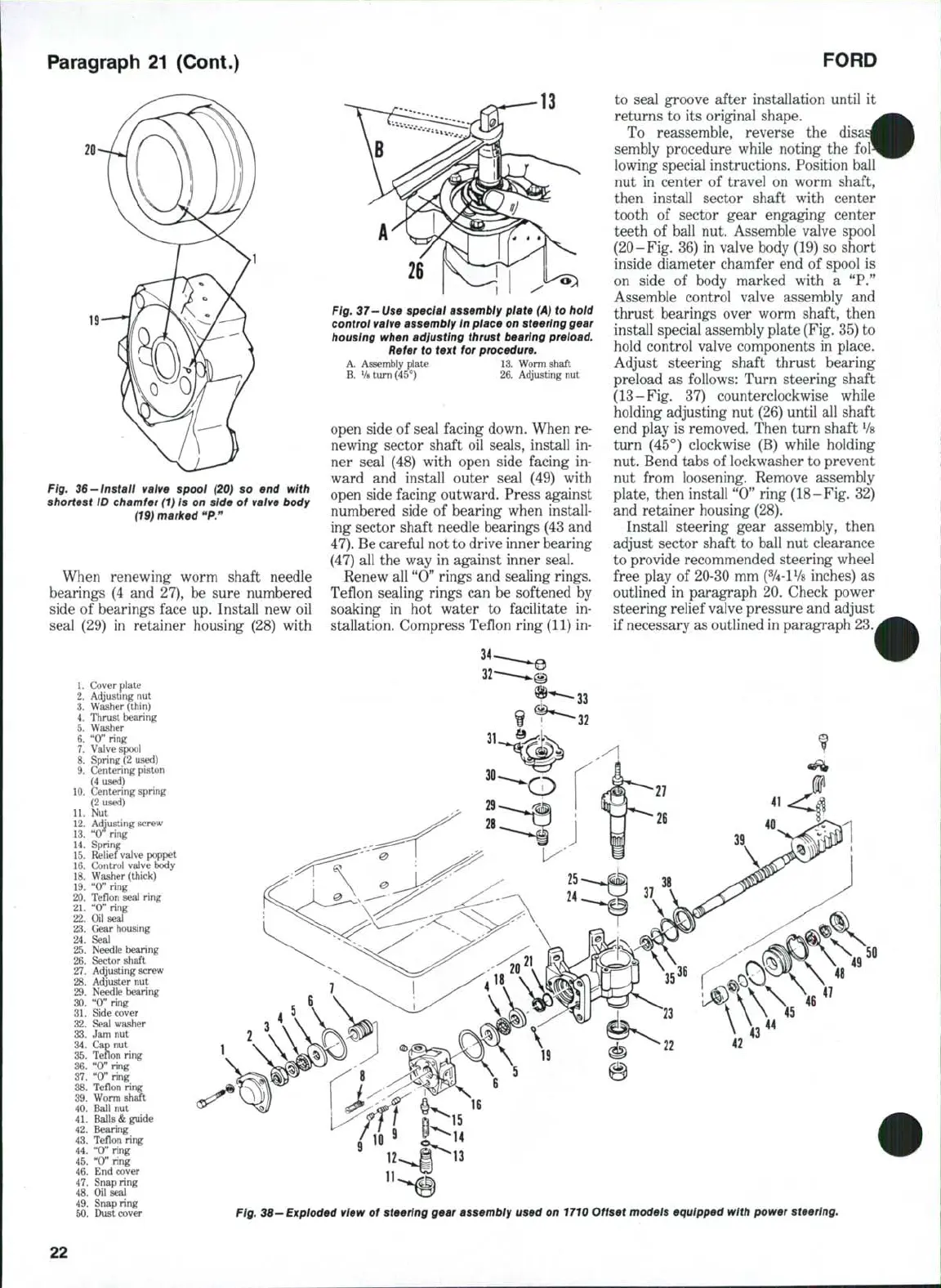
Fig. 37—Use special assembly plate
(A)
to hold
control valve assembiy in place on steering gear
housing when adjusting thrust bearing preload.
Refer to text for procedure.
A. Assembly plate
13.
Worm shaft
B.
V8
turn (45°)
26.
Adjusting nut
open side
of
seal facing down. When re-
newing sector shaft
oil
seals, install
in-
ner seal
(48)
with open side facing
in-
ward
and
install outer seal
(49)
with
open side facing outward. Press against
numbered side
of
bearing when install-
ing sector shaft needle bearings (43 and
47).
Be careful not to drive inner bearing
(47)
all
the way
in
against inner seal.
Renew all "0" rings and sealing rings.
Teflon sealing rings can
be
softened
by
soaking
in hot
water
to
facilitate
in-
stallation. Compress Teflon ring (11) in-
to seal groove after installation until
it
returns
to its
original shape.
To reassemble, reverse
the di;
sembly procedure while noting
the
lowing special instructions. Position ball
nut
in
center
of
travel
on
worm shaft,
then install sector shaft with center
tooth
of
sector gear engaging center
teeth
of
ball nut. Assemble valve spool
(20-Fig. 36)
in
valve body (19)
so
short
inside diameter chamfer
end of
spool
is
on side
of
body marked with
a "P."
Assemble control valve assembly
and
thrust bearings over worm shaft, then
install special assembly plate (Fig, 35)
to
hold control valve components
in
place.
Adjust steering shaft thrust bearing
preload
as
follows: Turn steering shaft
(13-Fig.
37)
counterclockwise while
holding adjusting nut (26) until
all
shaft
end play
is
removed. Then turn shaft
Vs
turn
(45°)
clockwise
(B)
while holding
nut. Bend tabs of lockwasher to prevent
nut from loosening. Remove assembly
plate, then install "0" ring (18-Fig.
32)
and retainer housing (28),
Install steering gear assembly, then
adjust sector shaft
to
ball
nut
clearance
to provide recommended steering wheel
free play
of
20-30 mm (%-lV8 inches)
as
outlined
in
paragraph 20. Check power
steering relief valve pressure and adjust
if necessary as outlined in paragraph 23.
Fig. 38—Exploded view of steering gear assembly used on 1710 Offset models equipped with power steering.
22
 Loading...

