Paragraphs 24-25
FORD
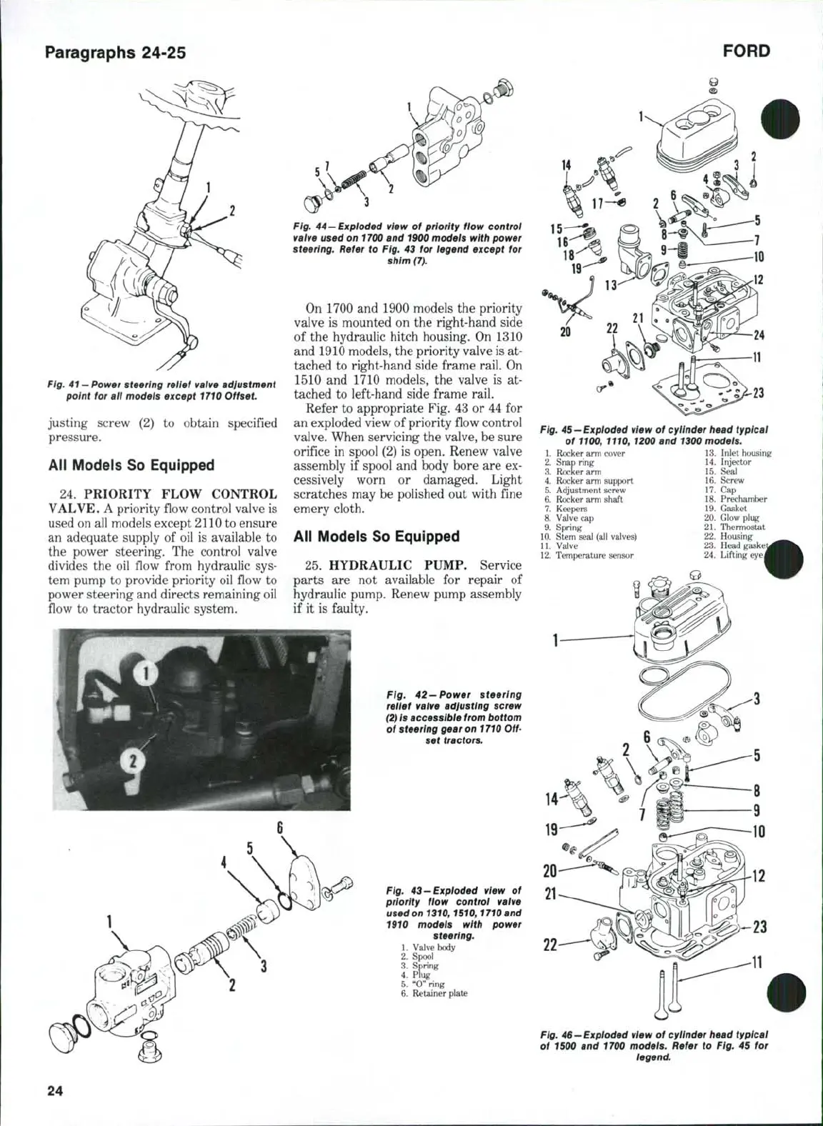
Fig.
41 —
Power steering relief valve adjustment
point for all models except 1710 Offset
justing screw (2) to obtain specified
pressure.
All Models So Equipped
24,
PRIORITY FLOW CONTROL
VALVE. A priority flow control valve is
used on all models except 2110 to ensure
an adequate supply of oil is available to
the power steering. The control valve
divides the oil flow from hydraulic sys-
tem pump to provide priority oil flow to
power steering and directs remaining oil
flow to tractor hydraulic system.
Fig.
44 —Exploded
view of priority flow control
valve used on
1700
and
1900
models with power
steering. Refer to Fig. 43 for legend except for
shim (7).
On 1700 and 1900 models the priority
valve is mounted on the right-hand side
of the hydraulic hitch housing. On 1310
and 1910 models, the priority valve is at-
tached to right-hand side frame rail. On
1510 and 1710 models, the valve is at-
tached to left-hand side frame rail.
Refer to appropriate Fig. 43 or 44 for
an exploded view of priority flow control
valve. When servicing the valve, be sure
orifice in spool (2) is open. Renew valve
assembly if spool and body bore are ex-
cessively worn or damaged. Light
scratches may be polished out with fine
emery cloth.
All Models So Equipped
25.
HYDRAULIC PUMP, Service
parts are not available for repair of
hydraulic pump. Renew pump assembly
if it is faulty.
Fig. 42-Power steering
reiief valve adjusting screw
(2)
is accessibie
from
bottom
of steering gear on
1710
Off-
set tractors.
Fig. 43-Exploded view of
priority flow control valve
used
on
1310,1510,1710 and
1910 models with power
steering.
1.
Valve body
2.
Spool
3.
Spring
4.
plug
5.
"0" ring
6. Retainer plate
14
Fig.
45-Exploded view of cylinder head typical
of 1100,1110, 1200 and 1300 models.
1.
Rocker arm cover 13. Inlet housing
2.
Snap ring 14. Injector
3.
Rocker arm 15. Seal
4.
Rocker arm support 16. Screw
5.
Adjustment screw . 17. Cap
6. Rocker arm shaft 18. Prechamber
7.
Keepers 19. Gasket
8. Valve cap 20. Glow plug
9. Spring 21. Thermostat
10.
Stem seal (all valves) " 22. Housing
11.
Valve 23. Head gaski
12.
Temperature sensor 24. Lifting eye.
Fig. 46-Exploded view of cylinder head typical
of 1500 and 1700 models. Refer to Fig. 45 for
legend.
24
 Loading...

