Paragraph 27 (Cont.)
FORD
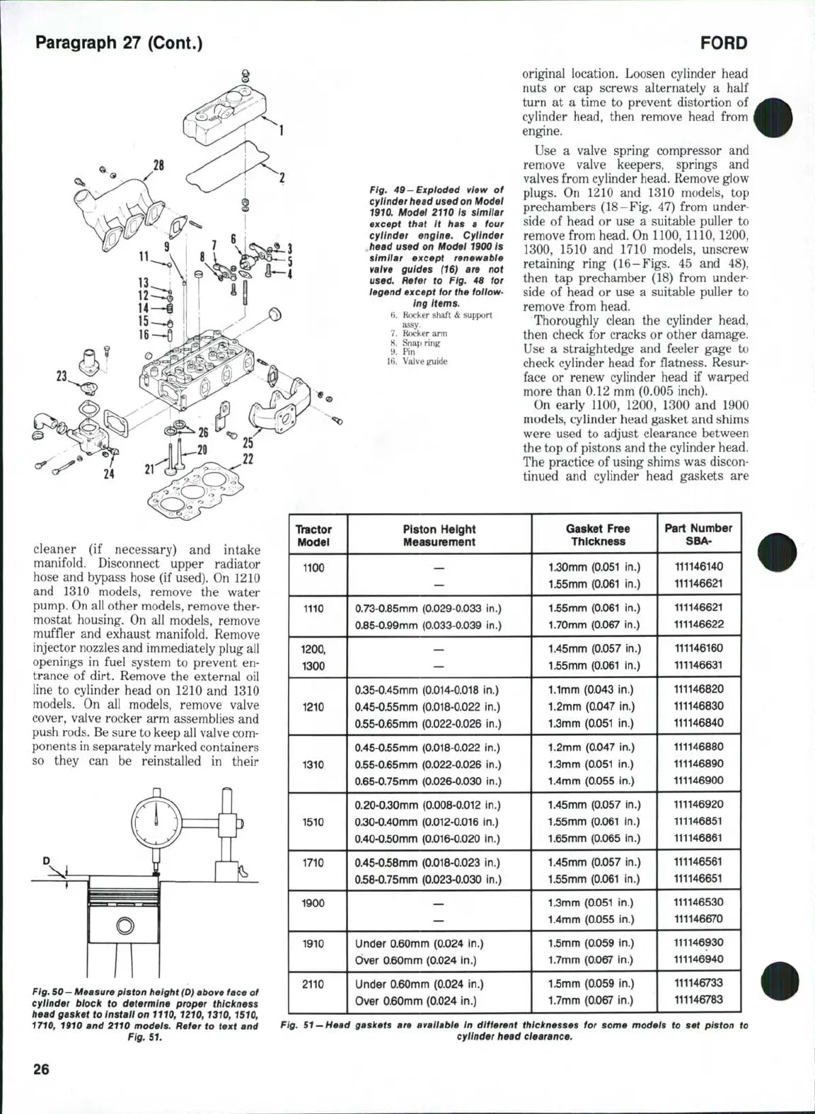
Fig. 49-Exploded view of
cyiinder head used on Model
1910. Model 2110 Is similar
except that It has a four
cylinder engine. Cylinder
head used on Model 1900 is
simiiar except renewabie
vaive guides (16) are not
used.
Refer to Fig. 46 for
legend except for the follow-
ing items.
6. Rocker shaft
&
support
assy.
7.
Rocker arm
8. Snap ring
9. Pin
16.
Valve guide
original location. Loosen cylinder head
nuts or cap screws alternately a half
turn at a time to prevent distortion of
cylinder head, then remove head from
engine.
Use a valve spring compressor and
remove valve keepers, springs and
valves from cylinder head. Remove glow
plugs.
On 1210 and 1310 models, top
prechambers (18-Fig, 47) from under-
side of head or use a suitable puller to
remove from head. On 1100, 1110,1200,
1300,
1510 and 1710 models, unscrew
retaining ring (16-Figs. 45 and 48),
then tap prechamber (18) from under-
side of head or use a suitable puller to
remove from head.
Thoroughly clean the cylinder head,
then check for cracks or other damage.
Use a straightedge and feeler gage to
check cylinder head for flatness. Resur-
face or renew cylinder head if warped
more than 0.12 mm (0.005 inch).
On early 1100, 1200, 1300 and 1900
models, cylinder head gasket and shims
were used to adjust clearance between
the top of pistons and the cylinder head.
The practice of using shims was discon-
tinued and cylinder head gaskets are
cleaner (if necessary) and intake
manifold. Disconnect upper radiator
hose and bypass hose (if used). On 1210
and 1310 models, remove the water
pump. On all other models, remove ther-
mostat housing. On all models, remove
muffler and exhaust manifold. Remove
injector nozzles and immediately plug all
openings in fuel system to prevent en-
trance of dirt. Remove the external oil
line to cylinder head on 1210 and 1310
models. On all models, remove valve
cover, valve rocker arm assemblies and
push rods. Be sure to keep all valve com-
ponents in separately marked containers
so they can be reinstalled in their
Fig.
50—
Measure piston height
(D)
above face
of
cyiinder block to determine proper thickness
head gasket to Install on
1110,
1210,1310,1510,
1710, 1910 and 2110 models. Refer to text and
Fig.
51.
Thictor
Model
1100
1110
1200.
1300
1210
1310
1510
1710
1900
1910
2110
Piston
Height
Measurement
—
0.73-0,85mm
(0.029-0.033 in.)
0.85-0,99mm
(0.033-0.039 in.)
—
0.35-0.45mm
(0.014-0.018 in.)
0.45-0.55mm
(0.018-0.022 in,)
0,55-0.65mm
(0.022-0.026 in.)
0.45-0.55mm
(0.018-0.022 in.)
0.55-0.65mm
(0.022-0.026 in.)
0.65-0.75mm
(0.026-0,030 in,)
0.20-0.30mm
(0.008-0.012 in.)
0.30-0,40nfim
(0.012-0.016 in.)
0.40-050mm
(0.016-0.020 in.)
0.45-0.58mm
(0,018-0.023 in.)
0.58-0,75nnm
(0.023-0.030 in.)
—
Under
0.60mm (0.024 in,)
Over
0.60mm (0.024 in.)
Under
0.60mm (0.024 in.)
Over
0.60mm (0.024 in.)
Gasket
Free
Thickness
1.30mm (0.051 in.)
1.55mm (0.061 in.)
1.55mm (0.061 in.)
1.70mm (0.067 in.)
1.45mm (0.057 in.)
1.55mm (0.061 in.)
1.1mm (0,043 in.)
1.2mm (0.047 in.)
1.3mm (0.051 in.)
1.2mm (0.047 in.)
1.3mm (0.051 in.)
1.4mm (0.055 in.)
1.45mm (0.057 in.)
1,55mm (0.061 in.)
1.65mm (0.065 in.)
1.45mm (0.057 in.)
1.55mm (0,061 in.)
1.3mm (0.051 in.)
1.4mm (0.055 in.)
1.5mm (0.059 in.)
1.7mm (0.067 in.)
1,5mm (0.059 in.)
1.7mm (0.067 in.)
Part
Number
SBA-
111146140
111146621
111146621
111146622
111146160
111146631
111146820
111146830
111146840
111146880
111146890
111146900
111146920
111146851
111146861
111146561
111146651
111146530
111146670
111146930
111146940
111146733
111146783
Fig.
51 —Head
gaskets are available In different thicknesses tor some models to set piston to
cylinder head clearance.
26
 Loading...

