Paragraphs 70-72
FORD
Fig, 128-View of throttle linkage adjustment
points for 1510 models.
1.
High idle stop screw
2.
Shut-off stop screw
Fig. 129-View of throttle linkage adjustment
points typical of 1500,1700,1710,1900,1910
and
2110 modeis.
1.
High idle stop screw
2.
Shut-off stop screw
Engine should shut off quickly when
throttle control lever is moved to STOP
position. If engine continues to run, turn
control arm stop screw (2) counter-
clockwise as necessary until engine
shuts off when control lever is moved to
STOP position.
GOVERNOR
Models 1100-1110-1200-1300
70.
The governor flyweights are
located on the forward end of engine
camshaft. The governor control linkage
is located inside timing gear case. To
service governor linkage or fiyweights,
refer to paragraph 33 for removal of
timing gear case. Refer to Fig. 132 for
exploded view of fiyweights and asso-
ciated parts. Refer to Fig. 133 for ex-
ploded view of linkage.
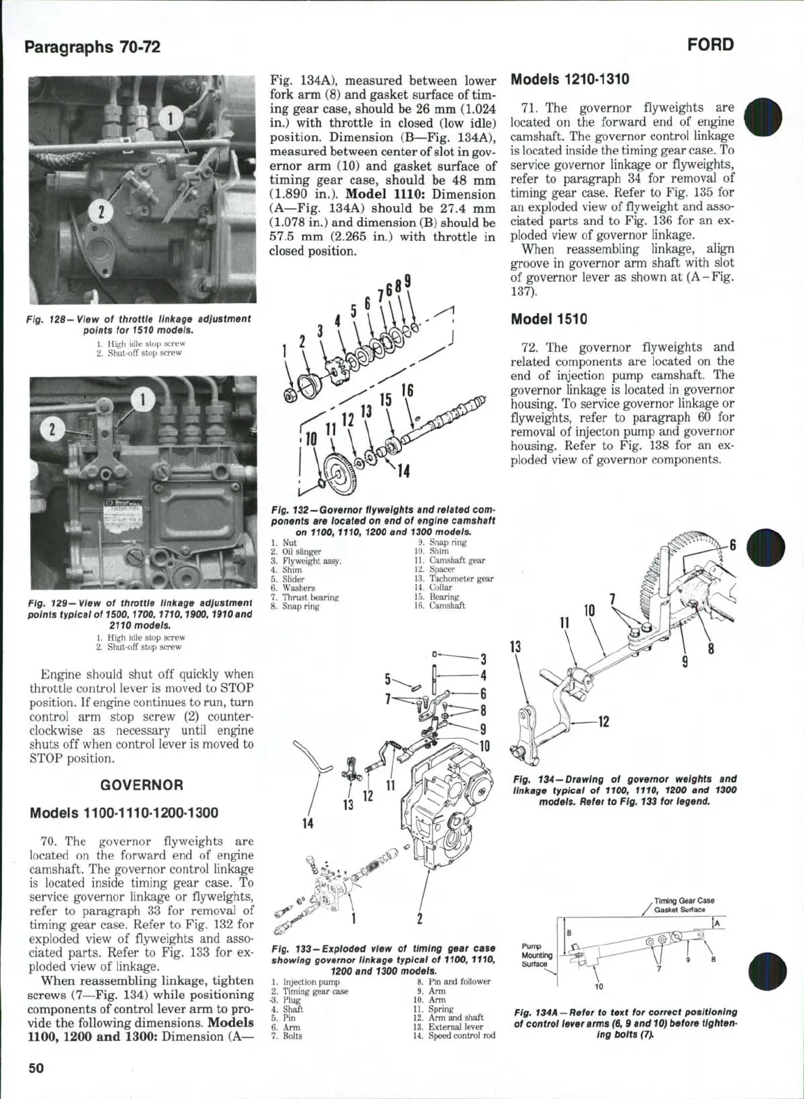
When reassembling linkage, tighten
screws (7—Fig. 134) while positioning
components of control lever arm to pro-
vide the following dimensions. Models
1100,
1200 and 1300: Dimension (A—
Fig. 134A), measured between lower
fork arm (8) and gasket surface of tim-
ing gear case, should be 26 mm (1,024
in.) with throttle in closed (low idle)
position. Dimension (B—Fig, 134A),
measured between center of slot in gov-
ernor arm (10) and gasket surface of
timing gear case, should be 48 mm
(1.890 in,). Model 1110: Dimension
(A—Fig. 134A) should be 27.4 mm
(1.078 in.) and dimension (B) should be
57,5 mm (2,265 in.) with throttle in
closed position.
Fig,
132—Governor
flyweights and related com-
ponents are located on end of engine camshaft
on 1100,1110, 1200 and 1300 models.
1.
Nut 9. Snap ring
2.
Oil slinger 10. Shim
3.
Flyweight assy. . 11. Camshaft gear
4.
Shlni 12. Spacer
5.
Slider 13. Tachometer gear
6. Washers 14. Collar
7.
Thrust bearing 15. Bearing
8. Snap ring 16. Camshaft
Fig, 133-Exploded view of timing gear case
showing governor linkage typical of
1100,
1110,
1200 and 1300 models.
1.
Injection pump
2.
Timing gear case
•3.
Plug
4.
Shaft
5.
Pin
6. Arm
7.
Bolts
8.
9.
10.
11.
12.
13.
14.
Pin and follower
Arm
Arm
Spring
Arm and shaft
External lever
Speed control rod
Models 1210-1310
71.
The governor flyweights are
located on the forward end of engine
camshaft. The governor control linkage
is located inside the timing gear case. To
service governor linkage or fiyweights,
refer to paragraph 34 for removal of
timing gear case. Refer to Fig. 135 for
an exploded view of fiyweight and asso-
ciated parts and to Fig. 136 for an ex-
ploded view of governor linkage.
When reassembling linkage, align
groove in governor arm shaft with slot
of governor lever as shown at
(A
- Fig,
137).
Model 1510
72.
The governor flyweights and
related components are located on the
end of injection pump camshaft. The
governor linkage is located in governor
housing. To service governor linkage or
fiyweights, refer to paragraph 60 for
removal of injecton pump and governor
housing. Refer to Fig, 138 for an ex-
ploded view of governor components.
13
Fig.
134
—Drawing
of governor weights and
linkage typical of 1100, 1110, 1200 and 1300
models. Refer to
Fig.
133 for legend.
.
Timing Gear Case
/
Gasket Surta
Fig.
134A
- Refer to text for correct positioning
of control lever arms (6,9 and
10)
before tighten-
ing bolts
(7),
50