Paragraphs 78-81
FORD
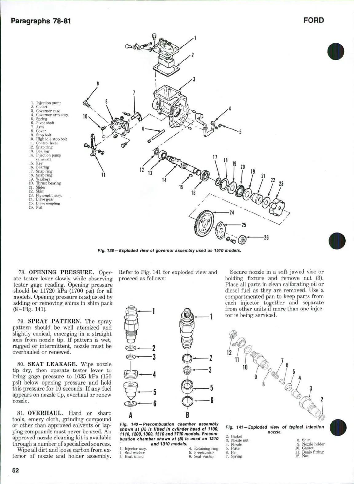
1. Injection pump
2.
Gasket
3.
Governor case
4. Governor arm assy,
5. Spring
6. Pivot shaft
7.
Arm
8. Cover
9. Stop bolt
10. High idle stop bolt
11.
Control lever
12. Snap ring
13.
Bearing
14. Injection pump
camshaft
15.
Key
16. Bearing
17.
Snap ring
18.
Snap ring
19. Washers
20. Thrust bearing
21.
Slider
22. Shim
23.
Flyweight assy.
24. Drive gear
25.
Drive coupling
26.
Nut
It
23
Fig,
138
—
Exploded
VIBW
of governor assembiy used on 1510 models.
78.
OPENING PRESSURE. Oper
ate tester lever slowly while observing
tester gage reading. Opening pressure
should
be
11720
kPa
(1700 psi)
for all
models. Opening pressure is adjusted by
adding
or
removing shims
in
shim pack
(8-Fig. 141).
79.
SPRAY PATTERN.
The
spray
pattern should
be
well atomized
and
slightly conical, emerging
in a
straight
axis from nozzle tip.
If
pattern
is
wet,
ragged
or
intermittent, nozzle must
be
overhauled
or
renewed.
80.
SEAT LEAKAGE. Wipe nozzle
tip
dry,
then operate tester lever
to
bring gage pressure
to
1035
kPa
(150
psi) below opening pressure
and
hold
this pressure
for
10 seconds.
If
any fuel
appears on nozzle tip, overhaul or renew
nozzle.
81.
OVERHAUL. Hard
or
sharp
tools,
emery cloth, grinding compound
or other than approved solvents
or
lap-
ping compounds must never be used. An
approved nozzle cleaning kit is available
through a number of specialized sources.
Wipe all dirt and loose carbon from ex-
terior
of
nozzle
and
holder assembly.
Refer to Fig. 141 for exploded view and
proceed
as
follows:
Fig, 140—Precombustion chamber assembiy
shown at (A) is fitted in cylinder head of 1100,
1110,1200,1300,1510 and
1710
models, Precom-
bustion chamber shown at
(B)
is used on 1210
and 1310 modeis.
1. Injector assy.
4.
Retaining ring
2.
S^
washer
5.
Prechamber
3.
Heat shield
6.
Seal washer
Secure nozzle
in a
soft jawed vise
or
holding fixture
and
remove
nut (3).
Place all parts in clean calibrating oil
or
diesel fuel
as
they
are
removed. Use
a
compartmented pan
to
keep parts from
each injector together
and
separate
from other units
if
more than one injec-
tor is being serviced.
Fig, 141-Exploded view of typical iniectlon
nozzle,
2. Gasket
3.
Nozzle
nut 8.
Shim
4. Nozzle
9,
Nozzle holder
5. Plate
10.
Gasket
6.
Pin 11.
Banjo fitting
7. Spring
12. Nut
52