15
An important factor in making a satisfactory weld is preparation. This includes studying the process and equipment
and practicing welding before attempting to weld finished product. An organized, safe, ergonomic, comfortable,
and well-lit work area should be prepared for the operator. The work area should specifically be free of all
flammables with both a fire extinguisher and a bucket of sand available.
To properly prepare for welding with your new welder, it is necessary to:
• Read the safety precautions at the front of this manual.
• Prepare an organized, well-lit work area.
• Provide protection for the eyes and skin of the operator and bystanders.
• Attach the ground clamp to the bare metal to be welded, making sure of good contact.
• Plug the machine into a suitable outlet.
• Completely open the gas cylinder valve. Adjust the gas pressure regulator to the correct flow rate. (Not
applicable to Stick “SMAW” process.)
EXPOSURE TO A WELDING ARC IS EXTREMELY HARMFUL TO THE EYES AND
SKIN. PROLONGED EXPOSURE TO A WELDING ARC CAN CAUSE BLINDNESS
AND BURNS. NEVER STRIKE AN ARC OR BEGIN WELDING UNLESS YOU ARE
ADEQUATELY PROTECTED. WEAR FIRE RESISTANT WELDING GLOVES, HEAVY
LONG SLEEVED SHIRT, CUFF-LESS PANTS; HIGH TOPPED SHOES AND A
WELDING HELMET.
• Press the PROCESS SELECTION BUTTON (1) on the front panel until the PROCESS INDICATOR LED (2) for Stick
(SMAW) welding is lit.
• Check the electrode packaging to determine the recommended polarity and connect the electrode holder and
ground clamp to the NEGATIVE (-) and POSITIVE (+) DINSE SOCKETS (10 and 11) accordingly.
• Direct current electrode positive (DCEP) or direct current reverse polarity (DCRP): electrode holder in
POSITIVE (+) DINSE SOCKET, ground clamp in NEGATIVE (-) DINSE SOCKET. Most electrodes use DCEP.
• Direct current electrode negative (DCEN) or direct current straight polarity (DCSP): electrode holder in
NEGATIVE (-) DINSE SOCKET, ground clamp in POSITIVE (+) DINSE SOCKET
• Ensure the ground clamp has a good connection to the workpiece and is connected on clean, bare metal (not
rusty or painted).
• Secure the bare end of the welding electrode in-to the jaws of the electrode holder.
• Switch the unit ON with the ON/OFF SWITCH (12).
• Set the amperage with the AMPERAGE ADJUSTMENT KNOB (6).
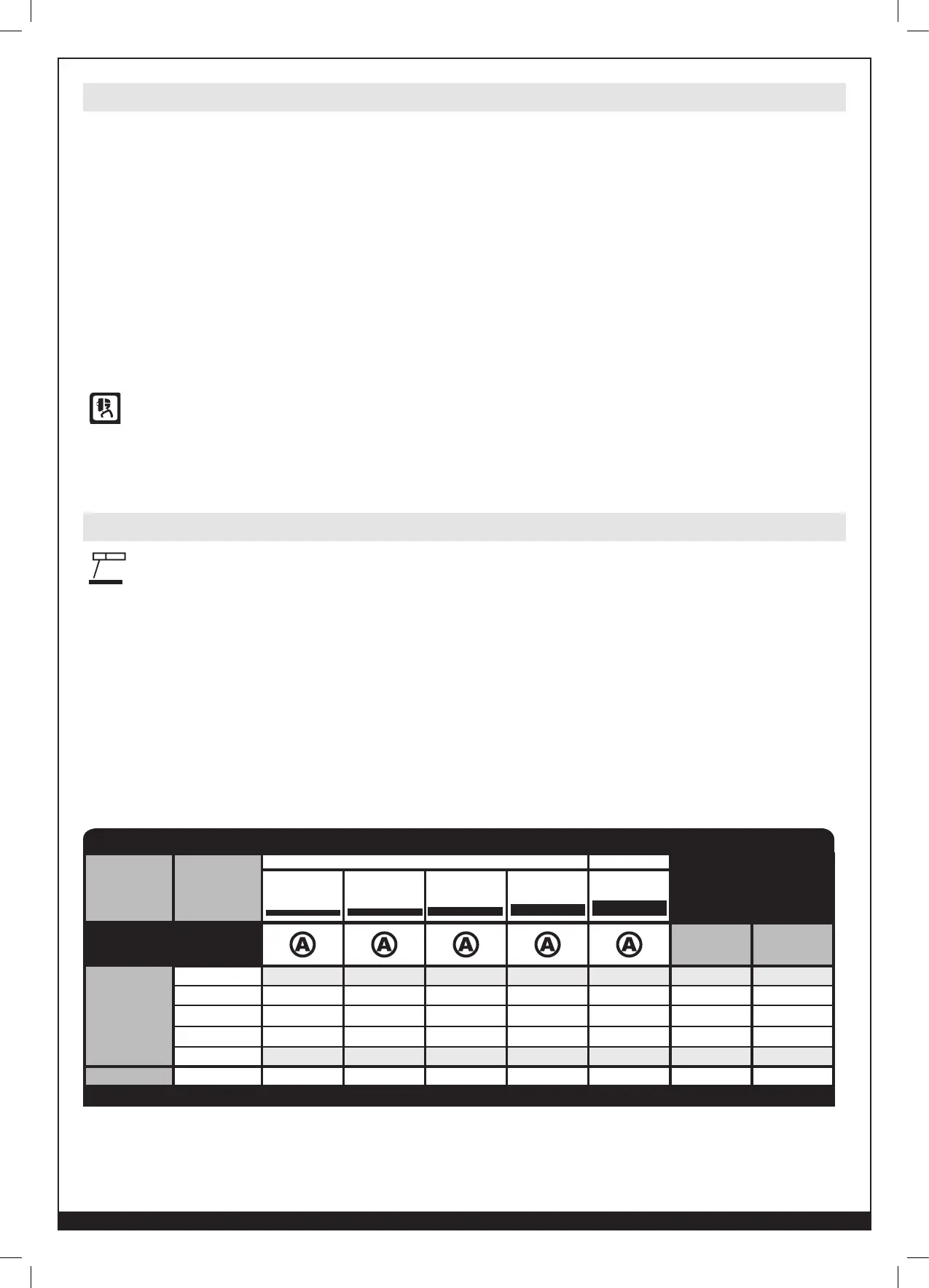
Regulation Knob Hz % On
Mild Steel
E6010 – – 30-75A 65-125A 80-160A 3.5-4 50-55
E6011 – – 30-75A 35-120A 80-160A 3.7-4.2 50
E6013 10-50A 30-80A 40-90A 50-130A 90-180A >5 >50
E7014 – 30-70A 40-90A 60-130A 90-180A 2-2.4 40-45
E7018 – – 50-80A 80-160A 90-180A 5.5-6.5 70
Stainless Steel
E308L – – 40-70A 50-80A 70-130A 4-7 50-90
CANNOT WELD ALUMINUM
MATERIAL
(Wire)
ELECTRODE
TYPE
ELECTRODE DIAMETER
PULSE RECOMMENDATION
1/16” (1,6 mm) 5/64” (2 mm) 3/32” (2,4 mm) 1/8” (3 mm)
5/32” (4 mm)
180 ST+ STICK SET-UP CHART
Welding Preparation
Setup for Stick Welding (SMAW)