Do you have a question about the Forney Easy Weld 261 and is the answer not in the manual?
Instruction to consult the user manual for detailed information and guidance.
Procedure for installing the correct wire spool, specifying diameter.
Guidance on setting the drive roll, emphasizing correct orientation.
Instructions for feeding wire and adjusting tension for proper grip.
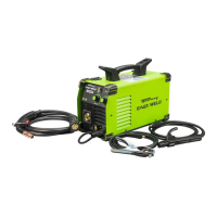
Details on connecting the welder to a power source, including voltage and generator requirements.
Steps to remove existing consumables and then replace them after wire feed.
Guidance on adjusting wire feed speed and voltage settings for welding.
Procedure for starting the welding arc by positioning the tip and pulling the trigger.
Interpreting the status of LED lights for machine operation and potential issues.
Clarifies that the machine is for flux-cored welding only and not for aluminum.
Addresses issues with circuit breakers tripping or exceeding duty cycle, suggesting solutions.
Diagnoses causes for low weld output or poor fusion, focusing on power input.
Covers improper wire spool installation and issues related to excessive spool tension.
Explains correct drive roll pressure to avoid wire slippage or damage.
Details why the arc may not start and emphasizes trigger engagement.
Highlights issues caused by mismatched drive rolls, liners, or contact tips.
| Model | Easy Weld 261 |
|---|---|
| Type | MIG Welder |
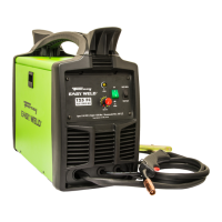
| Input Voltage | 120V |
| Amperage Range | 30-140A |
| Output Current Range | 30-140A |
| Maximum Material Thickness | 1/4 inch |
| Weight | 19 lbs |
| Processes | MIG |
| Welding Thickness | Up to 1/4 inch |
| Wire Feed Speed | 50 IPM |
| Wire Size | .030 inches |
| Duty Cycle | 90A @ 30% (MIG), 80A @ 30% (Stick), 100A @ 20% (TIG) |