3.1 Call button numbers and address
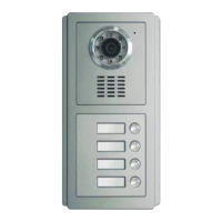
A, The door station and assistant door panels' call button numbers are ranked as the following figures.
No.0001
No.0002
No.0003
No.0004
Part 3 System programming
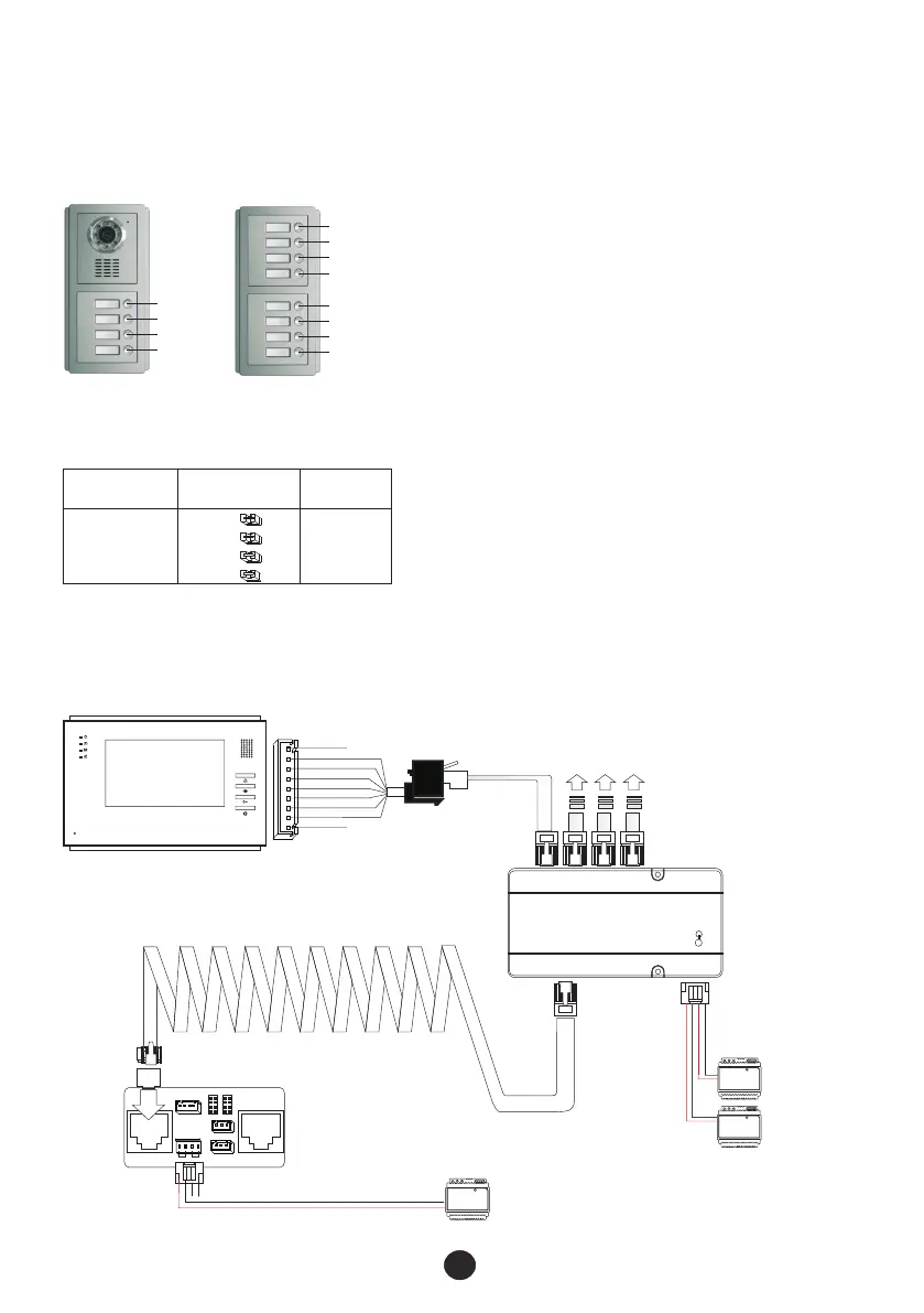
B, Assistant door panels' address (for 5-12 way only)
On the back of the assistant door panel there are 4 jumper couplers. Please ensure jumper setting is set as
below. If there is no assistant door panel, please ignore this part and go to next part directly.
10
Jumper couplers'
arrangement
Call button
No.
Address code
No.
0
SW1
SW2
SW3
SW4
0005~0012
No.0005
No.0006
No.0007
No.0008
No.0009
No.0010
No.0011
No.0012
3.2 Indoor phone address setting
3.2.1 Wiring
Prepare the cables and wire the necessary devices with the enclosed terminal connectors as the following
diagram. (If there is any assistant door panel, please connect it also.)
Video indoor phone
CALL
12VIN
G
AF
ETRXD
32VIN
V+
V-
ALM
12V+ 12 V- DATA
ALM G UL G
①
COM NC NO
12V+ 1 2V- L+ L-
JP3
JP1 JP2
JP4
JP8
JP6
JP5 1 JP2 1
12V- AU 3 2VIN V -
12V+ S GND ETR XD V+
R- T+ A+ V M-
R+ A- T- V M+
POWER U NLOCK
②
③
④
⑥
Isolation module
SGNG +32V G +12V
SOUT POUT INPUT
OUT-4 OUT-3 OUT-2 OUT-1
To other indoor
phones
Power supply
Power supply
PSU 32
PSU 12
Door station FTDEPC4
PSU 12
⑤