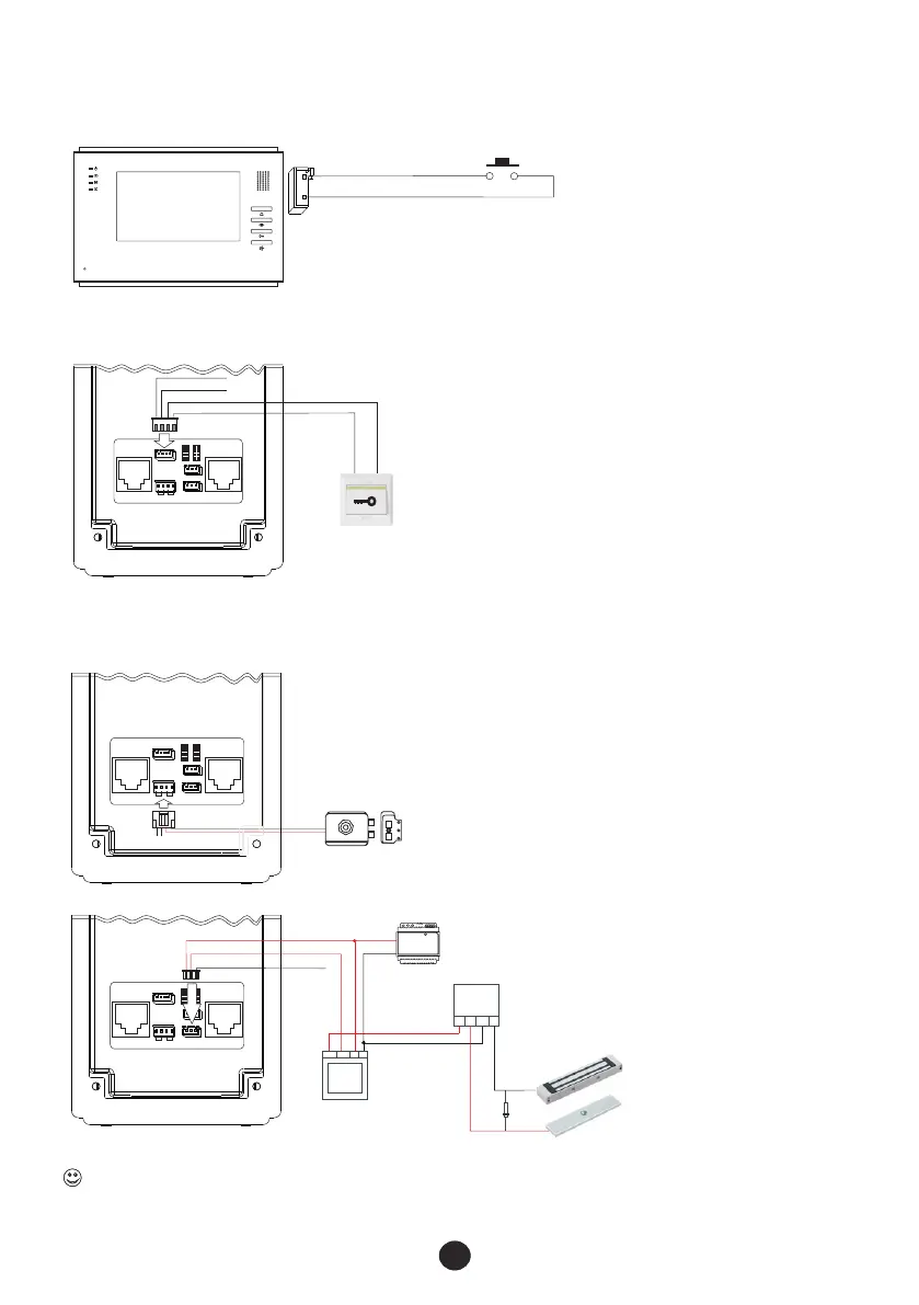
2.5 Connection diagram for other devices
2.5.2 Wiring diagram of EXIT push button
2.5.3
8
EXIT
push button
Momentary normally Open
Doorbell button
Video indoor phone
CALL
G
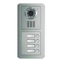
Door station FTDEPC4
ALM
G
UL
G
DOOR
EXIT
12V+ 12V - DATA
ALM G UL G
①
COM NC NO
12V+ 12 V- L+ L-
JP3
JP1 JP2
JP4
JP8
JP6
JP5 1 JP2 1
12V- AU 3 2VIN V-
12V+ SG ND ETRX D V+
R- T+ A+ V M-
R+ A- T- V M+
POWER UNLOCK
②
③
④
⑥
2.5.1 Wiring diagram of doorbell push button
Lock release
12V+ 12V - DATA
ALM G UL G
①
COM NC NO
12V+ 12 V- L+ L-
JP3
JP1 JP2
JP4
JP8
JP6
JP5 1 JP2 1
12V- AU 3 2VIN V-
12V+ S GND ETR XD V+
R- T+ A+ V M-
R+ A- T- V M+
POWER U NLOCK
②
③
④
⑥
⑤
⑤
Wiring diagrams of lock releases and electromagnetic locks
Door station FTDEPC4
COM
NC
NO
+
-
Electromagnetic lock
12V+ 12V - DATA
ALM G UL G
①
COM NC NO
12V+ 12 V- L+ L-
JP3
JP1 JP2
JP4
JP8
JP6
JP5 1 JP2 1
12V- AU 3 2VIN V-
12V+ S GND ETR XD V+
R- T+ A+ V M-
R+ A- T- V M+
POWER U NLOCK
②
③
④
⑥
Power supply
⑤
Touch
N/C C OM + -
+ + - -
+
_
DIODE
Break
glass
to
release
This device comes with a varistor. A varistor (or diode) must be connected across the lock terminal as the varistor controls the overload
produced by the strike coil or maglock. If not used then this may cause inerasable damage. If a maglock is to be used then an extra PSU,
break glass, push button to exit may be required. Please arrange according to your need.