4
B, Cable to door stations/modules
RVV2x1.0
(AWG18)
2
mm
Part 2 Connection
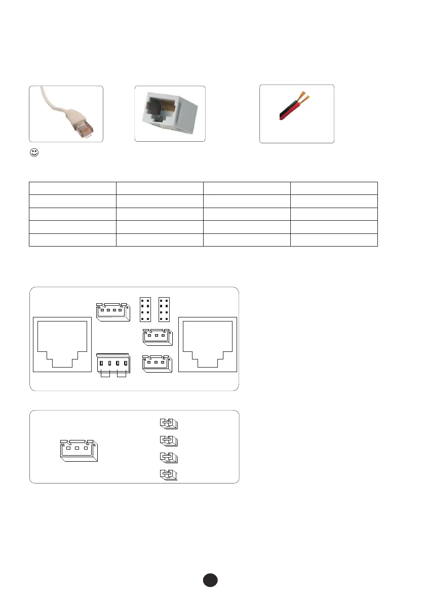
2.1 Cable requirements:
A, Cable from door station to modules/ indoor phones
RJ45 Port
CAT-5/E cable
Please follow TIA/EIA-568B Standard for CAT-5(E) cables to avoid interference.
Wires
Type(size)
Distance
Wire resistance
Door station to module
Modules to indoor phones
FTP-5E(1.5)
UTP-5(0.75)
RVV(2X1.0)
≤50m
≤10Ω
≤10Ω
<30m
2.2 Cables and distance
30m <
Min. gap:≥50cm, between low voltage and high voltage.
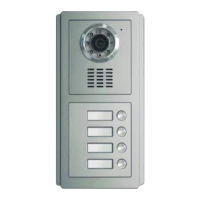
2.3 Terminals
EXT KEY
12V G DATA
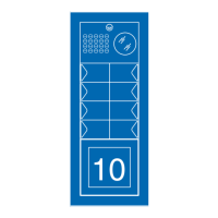
SW21
SW22
SW23
SW24
ADDR0
ADDR1
ADDR2
ADDR3
⑦
12V+ 12V- DATA
ALM G UL G
①
COM NC NO
12V+ 12V- L+ L -
Jp3
JP1 JP2
Jp4
JP8
Jp6
JP51 JP21
12V- AU 32VIN V-
12V+ SGND ETRXD V+
R- T+ A+ VM-
R+ A- T- VM+
POWER UNLOCK
②
③
④
⑥
A, Door station Model FTDEPC4
B, Assistant door panel Model FTDEP4, FTDEP8
①RJ45 port to isolation module.
②Standby.
③Terminals to power supply & e-lock(power type).
④Terminals to e-lock (signal type).
⑤
⑥
⑦
Terminals to EXIT push button.
Terminals between door station FTDEPC4 and assistant door panels.
Jumper couplers for coding assistant door panels.
Power supply to modules
Module to next module
FTP-5E(1.5)
<40m
(Please see details in 3.3.)
≤10Ω
⑤
⑥