1110
Rear - FGR-60F-3G4G SIM Slots - FGR-60F-3G4G
FGR-60F-3G4G
SIM1
Primary(1)
SIM2
Secondary(2)
SERIAL
RESET
+ -
+ -
DC2 12-125V
DC1 12-125V
DC1
DC2
SIM1
SIM2
SERIAL
RESET
+ -
+ -
DC2 12-125V
DC1 12-125V
DC1
DC2
SIM1
SIM2
SERIAL
RESET
+ -
DC 12-125V
SIM1
SIM2
SERIAL
RESET
+ -
DC 12-125V
SIM1
SIM2
SERIAL
RESET
+ -
DC 12-125V
SIM1
SIM2
SERIAL
RESET
+ -
DC 12-125V
SIM1
SIM2
1 2 3 4
NOTE: For more information on Wireless WAN Configuration, please
refer to the FortiOS Handbook at docs.fortinet.com
5
5
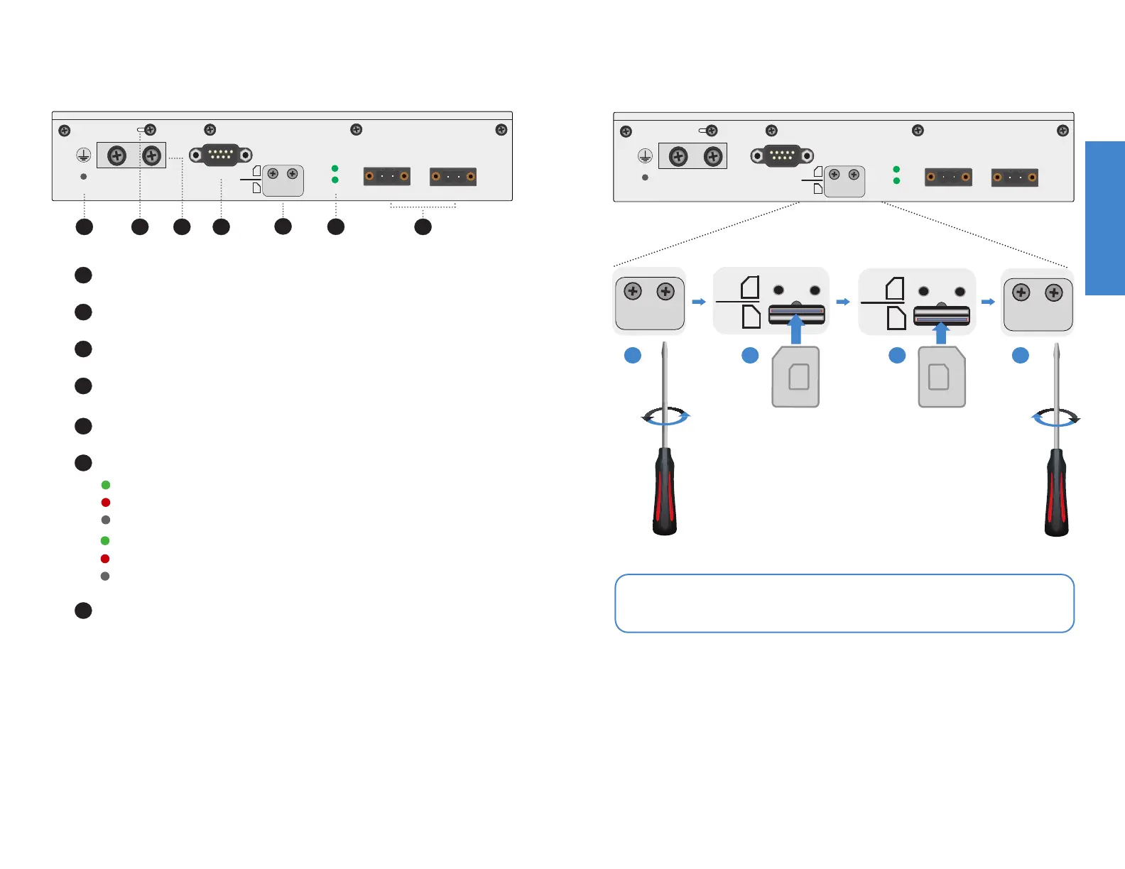
SIM Slots (2x Micro SIM) SIM card slots
2 3 4 7
6
1
1
2
3
4
RESET button
Ground Screw (#12 AWG) optional ground connection
Earth Ground (Lug Plate) ground connection
SERIAL Port (DB9) RS232 connection
6
7
Power Supply Indicators (DC1 & DC2) By default, Alarm is enabled in the OS*
Power Terminals (2 Pin Male) Redundant failover, 12V to 125V DC, 2A Max, see pg12
Green: Power supply is on
Red: Alarm is on*; power supply not providing power or not connected
Off: Power supply is off
Green: Power supply is on
Red: Alarm is on*; power supply not providing power or not connected
Off: Power supply is off
DC1
DC2

 Loading...