1312
Installation
Installation
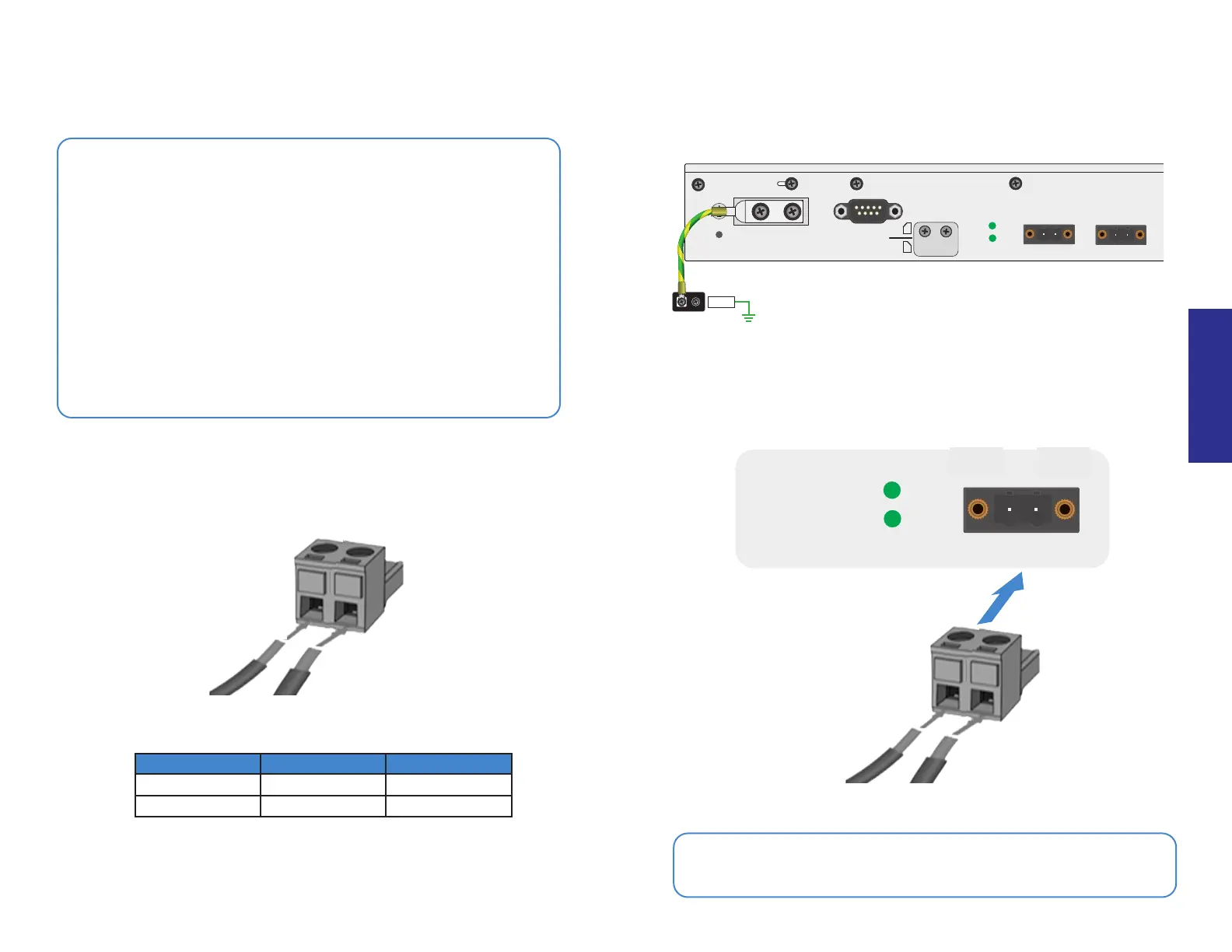
Power Connections
Warnings
• The DC input supports negative ground (+12V to +125V DC) and
positive ground (-12V to -125V DC) power sources
• Terminal +(A) is the high voltage potential pin and Terminal -(B) is
the lower voltage potential pin
• Do not connect +(A) to a lower voltage potential than -(B)
• The voltage between +(A) and -(B) must be +12V to +125V DC
• Consult a professional electrician to install the device and
determine a suitable wire gauge and length
• The DC terminal block wire gauge maximum is 12 AWG; the
minimum is 30 AWG
• Connect earth ground using the lug plate or grounding screw
• Install the supplied ferrite cores, see pg14
1. Connect +(A) of the device terminal block to the DC power source,
then connect the negative -(B) of the terminal block
2. Secure the earth ground terminal of the device to chassis
ground or earth ground
SERIAL
RESET
+ -
+ -
DC2 12-125V
DC1 12-125V
DC1
DC2
SIM1
SIM2
GND
3. Insert the wired terminal block into the power connector on the device
SERIAL
RESET
+ -
+ -
DC2 12-125V
DC1 12-125V
DC1
DC2
+(A)
+(A)
+(A) -(B)
-(B)
-(B)
DC Input Power +(A) Terminal -(B) Terminal
Negative Ground +12V to +125V DC Ground
Positive Ground Ground -12V to -125V DC
OPTIONAL: The FGR-60F Series have optional dual DC inputs for failover
redundancy. If a DC input fails, the second input will supply power.

 Loading...