3
Controller Operation - BIT25
The controller consists of two pieces, the controller (BIT25) and separate display (LCD5S).
The display is positioned inside the cabinet and the controller at the rear.
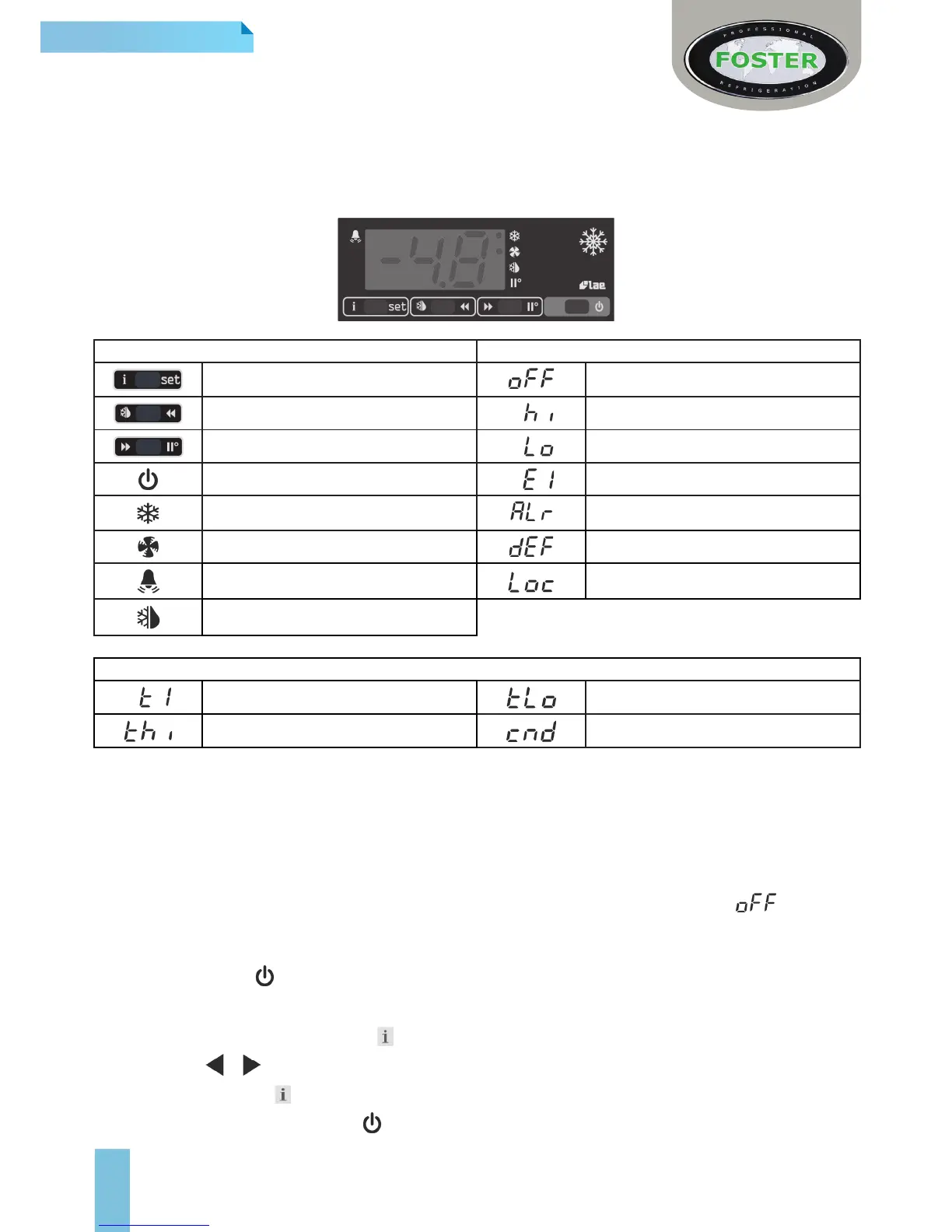
LCD5S Display Icons and Switches
Display Indicators & Buttons Alarms/ Warnings During Normal Operation
Info/ Set Point Button Controller in Standby
Manual Defrost/ Decrease Button Room High Temperature Alarm
Manual Activation/ Increase Button Room Low Temperature Alarm
Exit/ Standby Button Probe T1 Failure (Air)
Thermostat/ Compressor Output Generic Alarm
Fan Output Defrost In Progress
Alarm Warning Keypad Locked
Defrost Output
Information Menu Symbols and Reasons
Instant probe 1 temperature Minimum probe 1 temperature recorded
Maximum probe 1 temperature recorded Compressor working weeks **
** Displayed only if ACC > 0
Start Up and Operation
User Functions
Start Sequence
When the unit is rst connected to the mains the display will automatically light up and show either or the
current ambient temperature.
To start or activate when in standby:
> Press and hold the button for 5 seconds then release.
Access to the menu and information displayed
> Press and immediately release button
> With button or select the data to be displayed
> Press and hold button to display the value
> To exit from the menu, press button or wait for 10 seconds.