Setup Instructions
continued
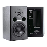
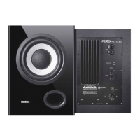
Back Panel Overview
Once the studio monitors have been placed in their final location, it is time to proceed to connecting
your PM841 / PM641 studio monitors to the mixing console or digital workstation. Connection to the
PM841 can be made using XLR or TRS connectors. The gain control on the back of the monitor
allows continuously variable adjustments to match most input types from -10dBV to +4dBu. The
input is electronically balanced and is compatible with unbalanced sources, although this may
require an adapter. The connection of the PM841 / PM641 to the console/digital workstation should
be done in the following order.
Step 1: Make sure that all equipment has been powered down.
Step 2: Confirm that all gain controls on the monitor and the source are set to the minimum.
Step 3: Connect the source to the PM841 / PM641 monitor.
Step 4: Power up all the source equipment and then turn on the PM841 / PM641 last.
Step 5: Set the gain of both monitors at medium setting and slowly bring up the gain of the console.
Step 6: Adjust the gain of both monitors for balance and for best signal to noise ratio.
Once the above steps have been completed, you are ready to use your PM841 / PM641 monitors.
It is recommended that you now play some familiar audio material and make any final adjustments,
as far as placement or level, to get the optimum performance in your monitoring environment.
1. Continuously variable gain control
This control adjusts the input level to the internal
amplifiers.
2. High Frequency Adjustment
Adjusts the high frequency characteristics around
10kHz within a ± 1dB range.
3. Low Frequency Adjustment
Adjusts the low frequency characteristics around
60Hz within a ± 3dB range.
4. TRS Balanced Input
5. XLR Balanced Input
These are an electronically balanced inputs and are
compatible with both -10dBV and +4dBu signals.
<CAUTION>: These inputs cannot be used simulta-
neously. The TRS input takes the priority and the
XLR input is disabled.
6. Heatsink
The heatsink dissipates heat from the amplifier. It is
important the heatsink receives proper ventilation
and is not placed near any sources of heat.
7. Power Switch
Turns power to the amplifier section on or off. On - position is the spot side.
8. Standard IEC Power Input
This power terminal should be used with a properly grounded three pin power cable, such as the one
provide with the product.
7
8
5
4
3
2
1
6
PM841 Rear Panel View
Product Specifications
Cable and Wiring Information
Product Cleaning Instructions
HOT (+)
XLR
PIN 2
PIN 3
PIN 1
TIP
RINGCOLD (-)
SHIELD (
GROUND
)
TRS
SHIELD
Prior to cleaning the PM841 / PM641 monitor, the power must be disconnected from the PM841 /
PM641 monitor. Once the power has been terminated, cleaning can be accomplished using a damp
(not wet) cleaning rag. A light common household cleaner can also be used, but care must be taken
not to use harsh cleaning fluids. Regular dusting or cleaning with a damp rag will keep your product
looking new for years.
Use high-quality, shielded cables to connect your mixing
console, workstation or other source to your monitors. Foil-
shielded cables should do quite well. Other high quality cables
that incorporate better shielding will yield an overall higher noise
rejection, lowering your systems susceptibility to external inter-
ference. Another important tip to keep in mind when wiring your
Product improvement may warrant a change of specifications, newer materials or cosmetics, Changes in specifications and features may
be made without notice or obligations.
<SPEAKER SECTION>
Enclosure System 3-way system
Drivers
Woofer
PM841 200 mm / 8”
PM641 165 mm / 6 1/2”
Mid range 100 mm / 4”
Tweeter 19 mm / 0.75” soft dome
Impedance
Woofer 8 Ω
Mid range 4 Ω
Tweeter 4 Ω
<AMPLIFIER SECTION>
Rated Output
Woofer
PM841 60 W
PM641 50 W
Mid range 18 W
Tweeter 18 W
Inputs
Connector ø6 mm TRS phone
(balanced)
XLR-3-31 (balanced)
Input level -10 dBV (TRS phone)
+4 dBu (XLR)
Impedance 20 kΩ or more
High & Low Adjustments
Low ±3 dB at around 60 Hz
High ±1 dB at around 10 kHz
Power Consumption
Normalmode 60 W
Stand-by mode 0.5W
Power Requirements
US/CND 120 VAC, 60 Hz
EUR/UK/AUS 230 VAC, 50/60 Hz
CHN 220 VAC, 50 Hz
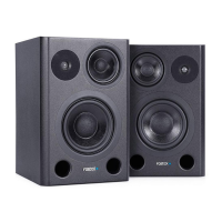
Frequency Response
PM841 50 Hz ~ 25 kHz
PM641 55 Hz ~ 25 kHz
<GENERAL>
Cabinet Dimensions
PM841
270.0 (W) x 423.0 (H) x 290.1 (D) mm incl. heatsink
253.5 mm (D) cabinet only
10.63” (W) x 16.65" (H) x 11.42" (D) incl. heatsink
9.98" (D) cabinet only
PM641
248.6 (W) x 375.6 (H) x 290.1 (D) mm incl. heatsink
253.5 mm (D) cabinet only
9.79” (W) x 14.79" (H) x 11.42" (D) incl. heatsink
9.98" (D) cabinet only
Net Weight
PM841 13.36 kg, 29.45 lbs.
PM641 11.10 kg, 24.47 lbs.
100 1k 10k
20 (Hz) 50 200 500 2k 5k 20k 50k
PM841 PM641
system is to route all line level cables away from the AC and other power sources, this will reduce the
probability of having AC hum emanating from your studio monitors.
 Loading...