- 24 - - 25 -
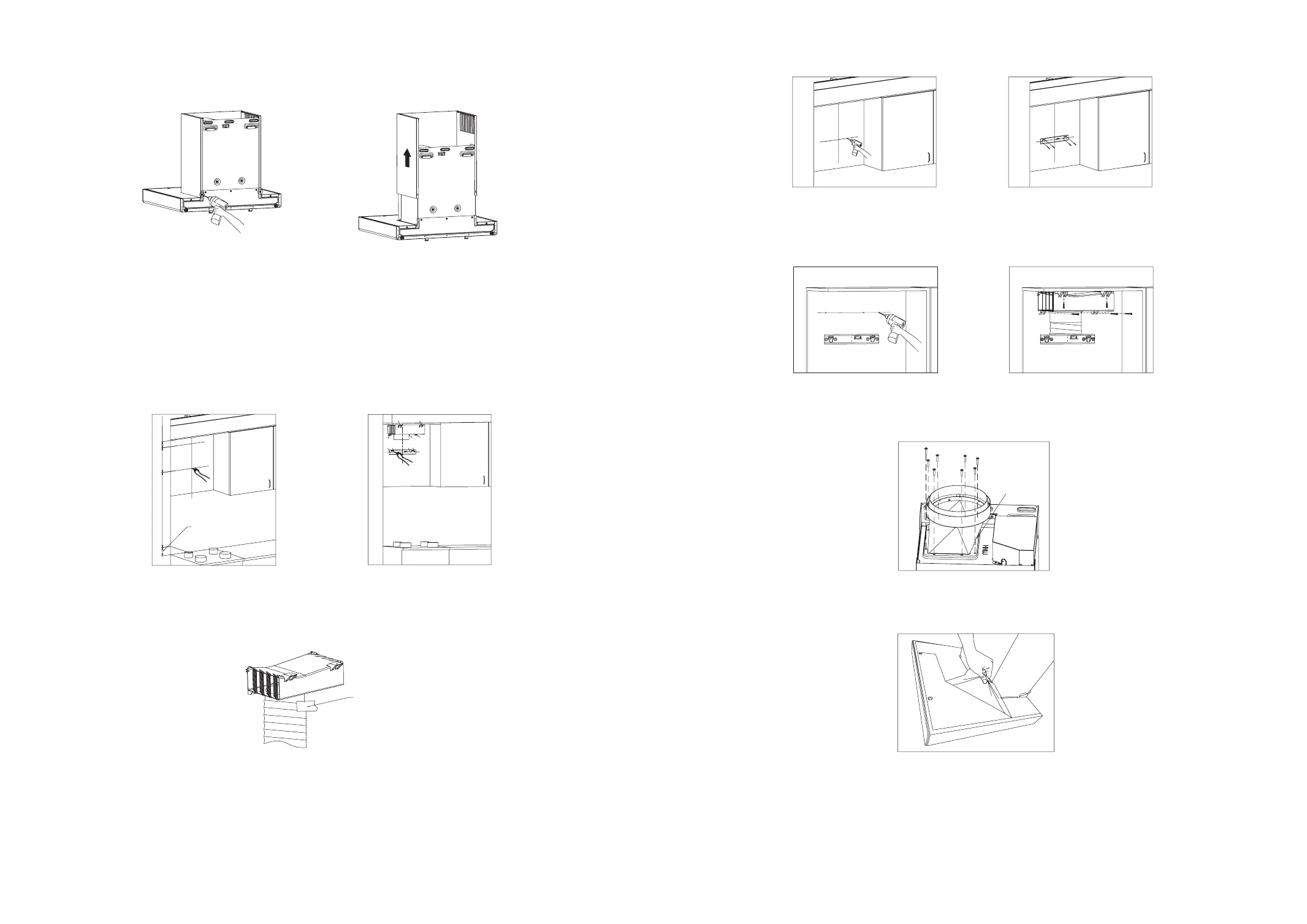
2. Remove the fan cover and decorative hood (only for EMS6008-C): remove the 2 screws that fix
the fan cover behind the main body with a screwdriver(see Fig.8), and then grab the fan cover and
decorative hood with both hands to take them out upward(see Fig.9);
Fig.8 Fig.9
3. Confirm the position used to fix the hook of main body and wind-guide box: first, draw a vertical
center line at the center point where the range hood to be installed, then take the supporting surface
of the cooking utensils on the stove as the reference point, accurately determine the installation
position of the hook of main body and wind-guide box on the solid wall, and make a punch mark.
The hook size of the main body is 1082mm-1132mm from the supporting surface of cooking utensils
on the stove to the bolt hole of the hook.
The size of the wind-guide box: the top surface of the wind-guide box shall be installed close to the
ceiling, the screw hole at the lower end of the wind-guide box shall be 118mm from the ceiling, and
the screw hole from the screw hole of hook of main body to the screw hole at the lower end of the
wind-guide box shall be ensured to be within the range of 186mm-341mm;
Distance from the
supporting surface of
cooking utensils on the
stove to the countertop
1082~1132
118
①② ③④
a
b
c
ed
Note: If ceramic tile, marble or glass and other decorative plates are found to protrude from the
mounting surface of the hook, please refer to Point 13 of “Installation Precautions” in P17 for
operation.
4. Fix the exhaust duct on the wind-guide box with foil tape;
Foil tape
5. Fix the hook of main body:
1) Ceramic tile (marble) at the drilling mark: drill φ 8mm hole at the drilling mark with electric drill,
then embed the ceramic tile expansion tube (5.3 × 32mm), x the hook with the hook screw (ST4.2
× 36mm), and make sure the hook is level with a level bar.
2) Gypsum board at the drilling mark: screw the gypsum board expansion tube (4 × 40mm) directly
into the wall surface with a screwdriver at the drilling mark, then x the hook with the hook screw
(ST4.2 × 36mm), and use a spirit level to make sure the hook is level.
6. Fix the wind-guide box: directly screw the gypsum board expansion tube (φ4×40mm) into the
wall surface with a screwdriver at the drilling mark (3 on the back wall and 2 on the ceiling), and then
x the wind-guide box with the hook screw (ST4.2 × 36 mm);
7. . Install the exhaust hood: x the exhaust hood and sealing ring at the air outlet of the main body with
8 exhaust hood screws (M4 × 18 mm);
The bevel
should towards
the electrical box
8. Remove the protective lm from the top plate surface;
9. Lift the main body, hang the back hook hole onto the hook, conrm the level of the main
body with a level bar, and x the fan frame and the hook with the fan frame screw (M4 ×
6mm);