
C
Carrie LoweJul 30, 2025
How to fix loose screws in Foundation FP-68KM4?
- CCatherine JohnsonJul 30, 2025
If you notice loose screws in your Foundation Air Conditioner, tighten them.
How to fix loose screws in Foundation FP-68KM4?
If you notice loose screws in your Foundation Air Conditioner, tighten them.
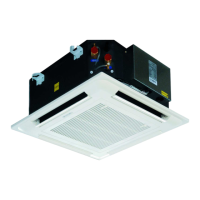
Manual for hydronic ceiling cassette fan coil units.
Specific model series covered by the manual.
Details regarding the 4-pipe system configuration.
Explanation of model naming conventions and code breakdown.
Key technical data including airflow, capacities, power, and dimensions.
Cooling capacity data for various models under different conditions.
Key parameters like Twi, Qw, Pf, Tad for cooling calculations.
Heating capacity data for various models under different conditions.
Key parameters like Twi, Qw, Pf, Tad for heating calculations.
List of accessories included with the fan coil unit.
Essential safety precautions for installation and servicing personnel.
Defines the operational limits for power supply and water circuits.
Covers installation site criteria, rooms to avoid, positioning, and maintenance access.
Steps for preparing ceiling panels and installing suspension bolts.
Procedure for marking, fitting suspension rods and brackets, and securing.
Instructions on temporary leveling and final tightening of nuts.
Steps for level ceiling installation and safely inserting the unit.
Methods for adjusting unit position and ensuring it is level.
Details on the condensate pump and flexible hose installation.
Instructions for installing the drain pipe with downward slope and insulation.
Procedure for connecting water pipes and using purge screws.
Steps for installing the external drain pan flush with the fixing plate.
Guidelines for wiring to avoid interference and ensure system stability.
Steps for front panel assembly and air filter removal/cleaning.
Essential checks before starting up the fan coil unit.
Safety, filter maintenance, and unit shut-down guidelines.
Details on accessing components and performing advanced maintenance.
Instructions for installing ductwork and identifying connection openings.
Table detailing branch duct dimensions (L x S) for different models.
Illustrations and specs for connecting ductwork and air openings.
Steps to find, prepare, and connect flanges to duct openings.
Detailed dimensional drawing for FP-68-80KM4 models.
Detailed dimensional drawing for FP-85-102-136KM4 models.
Detailed dimensional drawing for FP-170-204-238KM4 models.
Detailed list and diagram of components for FP-68-80KM4 models.
Detailed list and diagram of components for FP-85-102-136KM4 models.
Detailed list and diagram of components for FP-170-204-238KM4 models.
Explanation of remote controller buttons, LCD display, and operating modes.
Details on using Sleep, Mode, Fan Speed, and Timer functions.
Overview of wall pad controls and instructions for setting up master/slave units.
Defines terms, system operation, and computer control integration.
Explains cooling activation, termination, parameters, and coil protection.
Explains heating activation, termination, parameters, and coil protection.
Describes operation for dehumidification and automatic mode selection.
Details on heat mode activation, termination, pre-heat, post-heat, and coil protection.
Diagrams illustrating auto fan speed adjustment based on room temperature.
Covers louver control, buzzer notifications, auto restart, and manual operation buttons.
Detailed explanation of drain pump and float switch behavior in various conditions.
Description of LED lights indicating speed, modes, protections, and malfunctions.
Electrical wiring diagram for FP-68-80 KM4 units and its legend.
Electrical wiring diagram for other KM4 units and its legend.
Diagrams showing wiring for master-slave configurations and component connections.
Specifications and performance chart for the optional solenoid valve.
Details on connecting solenoid valves and required water quality.
Common issues like no start-up, insufficient output, and noise, with causes and actions.
Overview of connecting units to a computer system and centralizer features.
| Brand | Foundation |
|---|---|
| Model | FP-68KM4 |
| Category | Air Conditioner |
| Language | English |