7
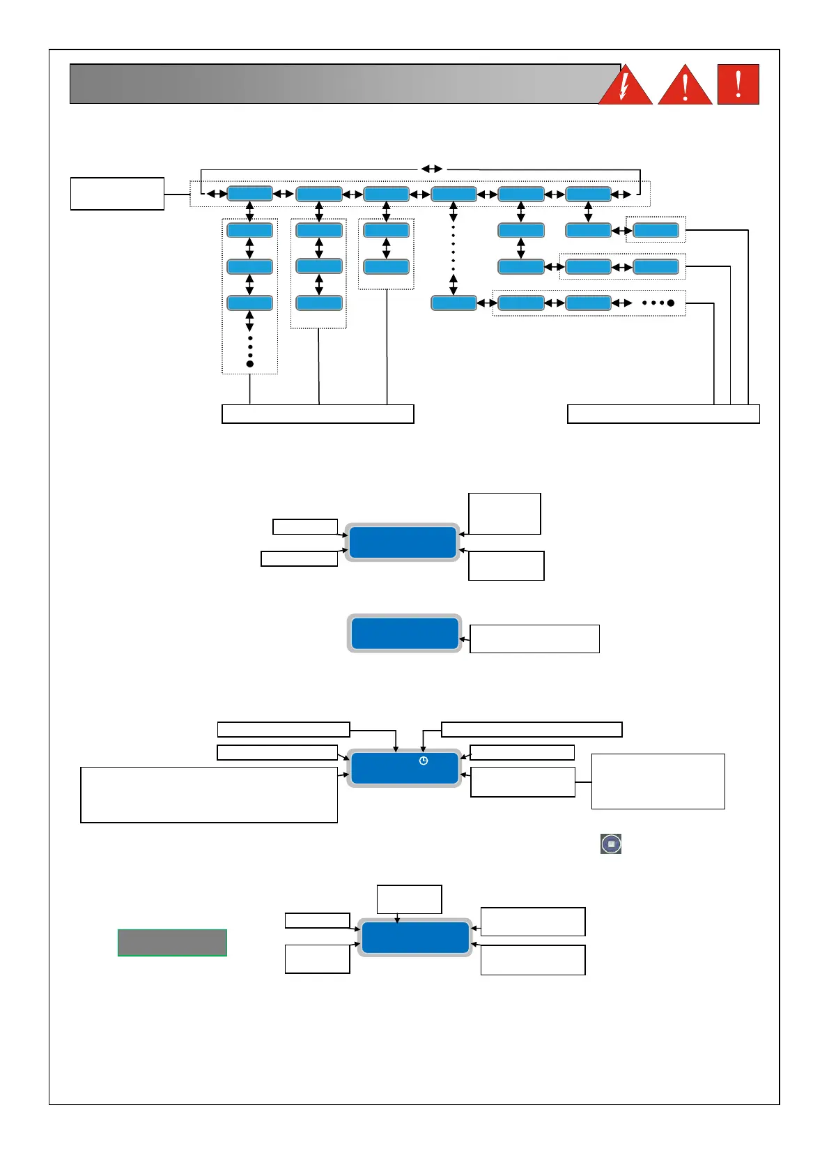
The overall menu settings are composed of a series of horizontal menus that allows access to sets of horizontal and
verticals parameters. As the following flowchart example:
NOTE: on the next page shows the complete flow chart programming
When the panel is turned on the display will light up:
Subsequently the start-up routine will execute:
At the end of the start-up routine the display will show following default main display:
The main default display shows the current working parameters. By pressing the button
is possible to move to
different screens and show the working parameter of the individual pump
7. DISPLAYS
HORIZONTAL
MENU’
VERTICAL PARAMETERS HORIZONTAL PARAMETERS
SOFTWARE
REVISION
YEAR
SOFTWARE
REVISION
MODEL
LANGUAGE
WAIT TIMER DELAY
RETURN POWER
Extreme
2015
(I) Rev.XX
Extreme
2015
(I) WaitXXsec
P1 X.XA St XXX
Cosφ X.XX h XXX
NUMBER OF
STARTS
HOURS OF
OPERATION
PUMP 1
COSφ
MEASURED
CURRENT
MEASURED
XTREME¹
XXXV 50Hz gsm
Lev 0.00m Dig
GSM PRESENCE
OPERATING
MODE
MAINS VOLTAGE
cln= CLEAN
drk= DARK
dig= DIGIT
p/w= PAUSE/WORK
MEASUREMENT SIGNAL 4-20mA (if enabled)
or PAUSE/WORK TIME IN MINUTES FOR
EACH PUMP (if activated its plan of
operation)
MAINS FREQUENCY SELF-
EST PUMP
ACTIVE