Do you have a question about the Fourgroup Full-App 2 and is the answer not in the manual?
Explains danger, warning, and caution symbols for potential hazards and operational advice.
Provides information for proper installation, use, and maintenance of the FULL-APP 2 unit.
Instructions for careful handling, proper storage, and visual inspection after unpacking.
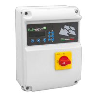
Describes the FULL-APP2 panel, its general features, and configurable settings.
Details the CLEAN, DARK, DIGIT, and MULTITANK operating modes for pump control.
Guidance on fixing the control panel and securing cables, including safety notes.
Instructions for connecting the line of supply current and motor power supply.
Attention to display connection, panel opening, and proximity to flammable liquids.
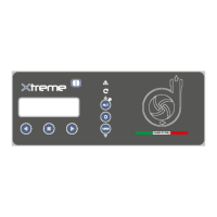
Explains the functionality of each button on the control panel interface.
Explains the meaning of the LED indicators for automatic mode, alarms, and power status.
Illustrates the horizontal and vertical parameter navigation structure.
Details the display sequence upon power-on and the default main display.
Describes how to access and view parameters for Pump 1 and Pump 2.
How to enter programming mode, handle passwords, and navigate menus.
Step-by-step guide to changing parameter values and saving the settings.
How to choose the language for alarm messages and the factory default.
Setting a delay before reactivating the control panel after a power cut.
Activating/deactivating the 4-20mA signal reading device for DIGIT mode.
Selecting units for 4-20mA sensor display (bar or meters).
Setting the full scale range for the 4-20mA sensor.
Enabling pump start when maximum level/pressure is reached via 4-20mA.
Choosing between auto or manual setting for the 4-20mA sensor's relative zero.
Automatically setting the relative zero for level/pressure for the 4-20mA sensor.
Manually setting the relative zero for the 4-20mA sensor.
Setting level/pressure to trigger a minimum alarm and stop pumps.
Setting level/pressure thresholds to start Pump 1 or Pump 2.
Setting level/pressure thresholds to stop Pump 1 or Pump 2.
Setting level/pressure to trigger a maximum alarm.
Adjusting delay for 4-20mA signal reading to stabilize it.
Deciding the functionality of the alarm float for consensus alarm.
Setting a time delay for the restart of pumps after the starting condition is met.
Setting a time delay for stopping pumps after the stopping condition is met.
Activating/deactivating alarms relative to Mains Power Voltage (Vmax, Vmin).
Setting a delay time for the activation of the voltage alarm.
Setting Mains Frequency and managing frequency difference alarms.
Setting timer for periodic self-test and its duration for pumps.
Setting the operating mode for manual buttons (Operator Presence vs. Timed).
Setting max simultaneous pumps and pump rotation modes.
Setting a timer for swapping pump starting priority.
Configuring delays for automatic restarts after dry running alarms (Restart 1-3).
Configuring delay for the 4th restart and option to exclude further restarts.
Setting inactivity time for display timeout and programming password.
Setting all operational parameters relative to Pump 1.
Setting all operational parameters relative to Pump 2.
Setting time delays for Pump 1 alarms related to current and Cosø.
Enabling/disabling the alarm for maximum continuous pump operation.
Setting the maximum time of continuous pump operation before alarm.
Enabling/disabling and setting max starts per minute alarm.
Enabling/disabling and setting max starts per hour alarm.
Enabling/disabling alarm for maximum Klixon events on the pump.
Setting the maximum number of Klixon events Pump 1 can handle.
Enabling/disabling and setting max working hours for maintenance alert.
Automatically setting main electrical parameters (current, Cosø) for Pump 1.
Setting the maximum allowed current consumption (overcurrent) for Pump 1.
Setting minimum current and Cosø values for Pump 1.
Copying all configured Pump 1 parameters to Pump 2.
Activating/deactivating the DARK operating mode for pumps.
Activating/deactivating the CLEAN operating mode for pumps.
Activating/deactivating the DIGIT operating mode for pumps.
Activating/deactivating the MULTITANK operating mode for pumps.
Setting the operating mode for DARK program to empty or fill.
Enabling or disabling the DARK operating mode for all pumps.
Enabling or disabling the CLEAN operating mode for all pumps.
Setting the operating mode for DIGIT program to empty or fill.
Enabling or disabling the DIGIT operating mode for all pumps.
Selecting operating modes (CLEAN, DARK, DIGIT) for Pump 1.
Selecting operating modes (CLEAN, DARK) for Pump 2.
Enabling or disabling the MULTITANK operating mode.
Assigning a name to the control panel/system for SMS replies.
Enabling or disabling the GSM modem functionality.
Setting the first phone number for SMS messages and remote control.
Setting the second phone number for SMS messages and remote control.
Setting the third phone number for SMS messages and remote control.
Verifying GSM communication with the entered phone numbers.
Setting the operating mode (Off, On, Pulsed) for the audio alarm output.
Setting which specific alarms activate the sound alarm output.
Table detailing 18 alarm types and their activation settings for outputs.
Setting the operating mode for the visual alarm output.
Setting the operating mode for the Q1 alarm output relay.
Setting the operating mode for the Q1 alarm output relay 2.
Defining which alarms send SMS and to which phone numbers.
Diagram showing connections for sound alarm, 4-20mA input, relays, and probes.
Connections for commands, protection inputs, Klixon, and level probes.
Details connections for supply, visual alarm, and inputs on the GSM board.
Step-by-step guide for inserting the SIM card into the GSM module.
Explains the meaning of LED indicators for GSM status.
Describes the additional input for max level alarm during black-out events.
Example connection diagrams for DARK mode in empty and fill tank scenarios.
Example connection diagrams for CLEAN mode in empty tank scenarios.
Example diagram for CLEAN mode with Cosø measurement in empty tank.
Example connection diagram for CLEAN mode in fill tank scenario.
Example connection diagram for DIGIT mode in empty tank scenario.
Example diagram for DIGIT mode with 4-20mA input in empty tank.
Example connection diagram for DIGIT mode in fill tank scenario.
Example for MULTITANK with two CLEAN pumps in empty tanks.
Example for MULTITANK with CLEAN and DARK pumps in empty tanks.
Example for MULTITANK with two DARK pumps in empty tanks.
Example for MULTITANK with DIGIT and CLEAN pumps in empty tanks.
Lists the various ways the motor stop can occur (manual, automatic, interlock).
Notes no routine maintenance required; work by qualified personnel only.
Customer responsibility for proper disposal according to local regulations.
Guidelines for ordering and using original spare parts to avoid issues.
States compliance with EU directives and harmonized standards.
Identifies the person authorized to compile technical documentation.
Defines terms for quotes, orders, and binding sales agreements.
Specifies conditions for prices, payment schedules, and delivery deadlines.
Outlines procedures and costs related to order suspension or cancellation.
Covers procedures for claims, warranty terms, exclusions, and liability limitations.
Defines governing law, jurisdiction, and agreement formalities.
| Brand | Fourgroup |
|---|---|
| Model | Full-App 2 |
| Category | Control Panel |
| Language | English |