39
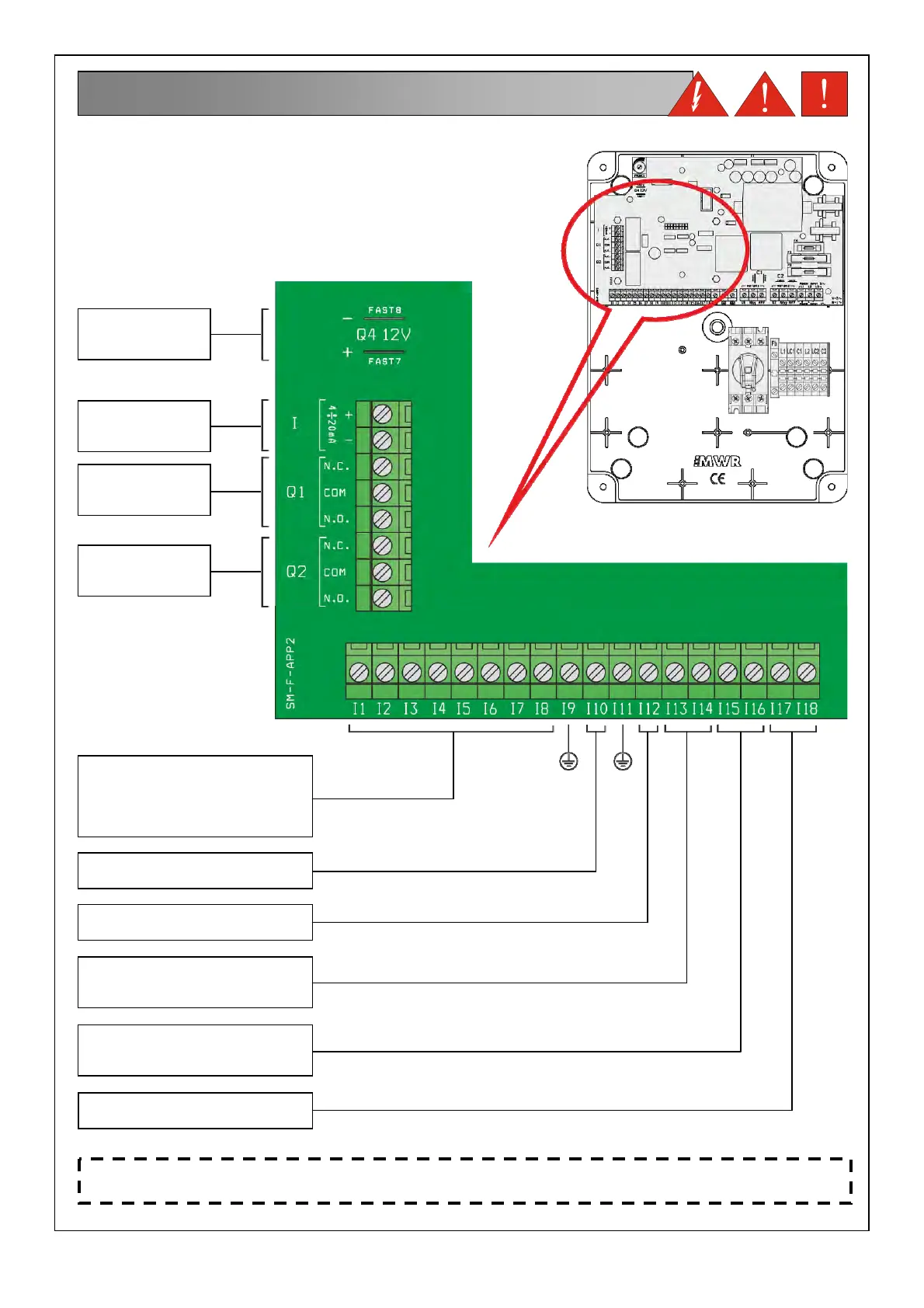
Connection of the control signals and protection on the main board
15. ELECTRIC CONNECTIONS
RELAY 1
ALARM OUTPUT
(dry contacts)
RELAY 2
ALARM OUTPUT
(dry contacts)
DEVICE
4-20mA
INPUT
COMMANDS AND PROTECTION
PUMPS INPUTS
(the connections change
depending on the operating mode;
see installation examples section)
PROBE FOR WATER IN OIL
CHAMBER PUMP 1 INPUT
PROBE FOR WATER IN OIL
CHAMBER PUMP 2 INPUT
KLIXON ALARM CONTACT
(NC) PUMP 1 INPUT
(ponticellare se non si collega)
KLIXON ALARM CONTACT
(NC) PUMP 2 INPUT
(ponticellare se non si collega)
SOUND
ALARM OUTPUT
(12V-30mA)
MAX LEVEL ALARM
CONTACT (NO) INPUT
NOTE: For proper operation of the water in the oil chamber detections probes (if installed), make sure
that the earth (PE) of the pumps is equipotential to the earth (PE) of the control panel.